
Architecting a Highly Available, Scalable, and Secure WordPress Platform on AWS
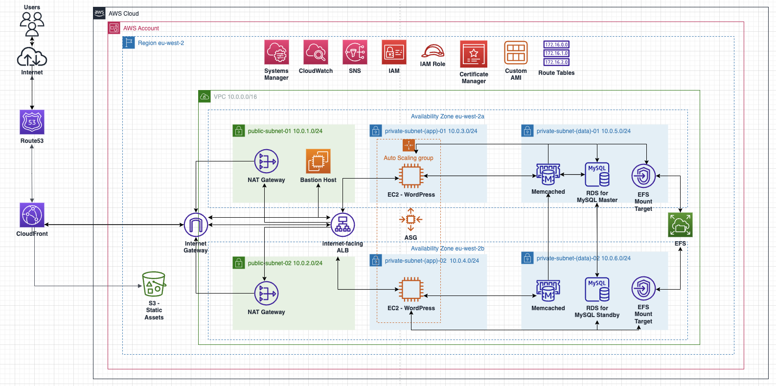
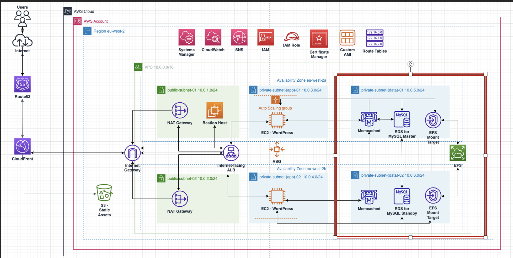
In this section, will create the resources shown on part of the diagram:
An Amazon Virtual Private Cloud (VPC) with an AWS Region
2 Public Subnets and 4 Private Subnets
An Internet Gateway (IGW)
A NAT Gateway (NGW)
Route Tables
Key Concepts
Amazon Virtual Private Cloud (VPC)
A VPC is a virtual network which is isolated from other networks within the cloud; providing a space to deploy your AWS resources. A VPC can span multiple Availability Zones within a region and has a specified IP (CIDR) range which you choose. This IP range of the VPC can be broken down into smaller isolated segments called Subnets. Whilst a VPC can span an entire region, subnets are bound to only 1 Availability Zone within the region.
Internet Gateway (IGW)
An IGW is a VPC components which allows 2-way communication between your VPC/chosen subnets and the internet. An IGW is attached to any VPC which you choose, however each subnet is deemed Private unless Routing is in place specifically to the IGW & that the resources within the subnet(s) have a globally unique public IPv4/IPv6 address.
Public/Private Subnets
By default, all subnets, when originally created, are seen as Private Subnets. Subnets are only called “Public” once they have access to an IGW and, therefore, have access to the internet.
Route Tables
A route table is essentially a set of rules which dictates where traffic within your VPC flows to/from. By default, all subnets within the same VPC have Local routing, however if we wish to send traffic to another VPC from a certain subnet, then we need to add the relevant rules into the subnets Route Table.
Creating the VPC
- Set your region in the top right-hand corner of the console to Europe (London) – EU-West 2
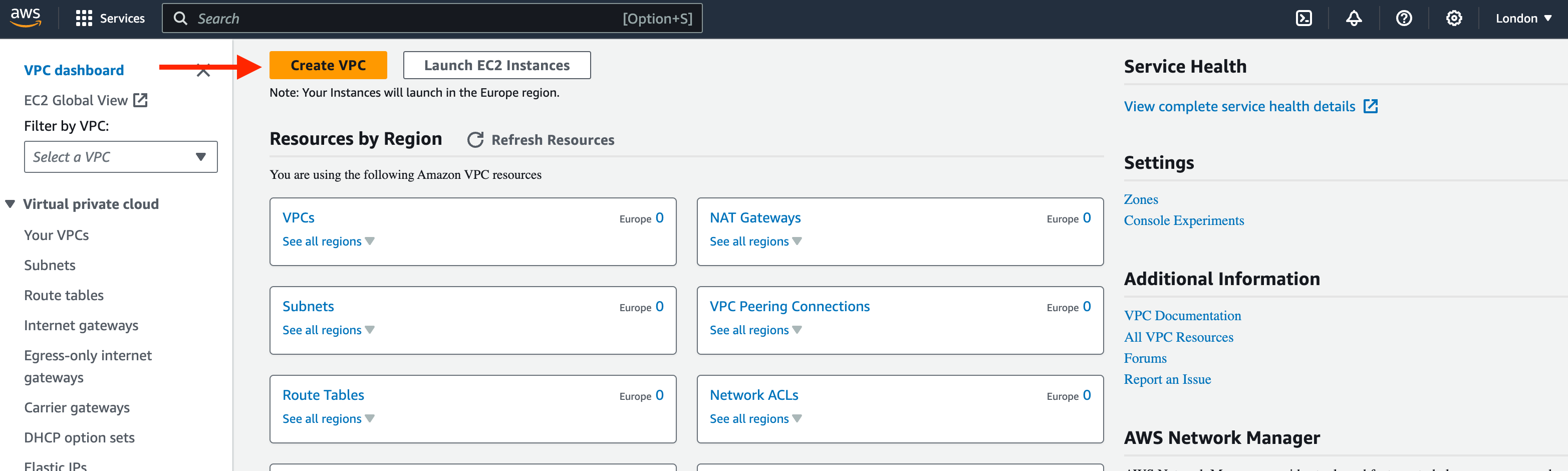
2. In the search bar, search for ‘VPC’
3. From ‘VPC Dashboard’, select ‘Create VPC’
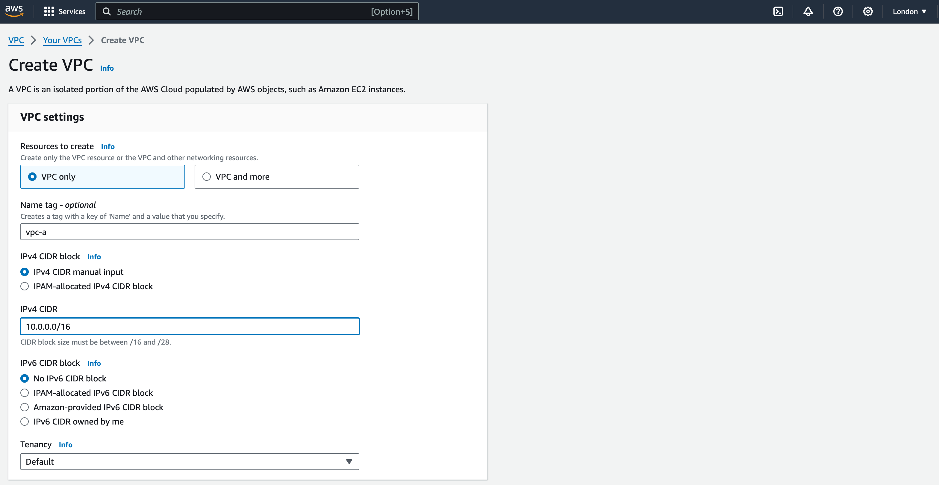
4. Select ‘VPC Only’
5. Name tag: ‘vpc-a’
6. IPv4 CIDR Block: keep the default setting – ‘IPv4 CIDR manual input’
7. IPv4 CIDR: input the CIDR as ‘10.0.0.0/16’. Leave all other settings as Default
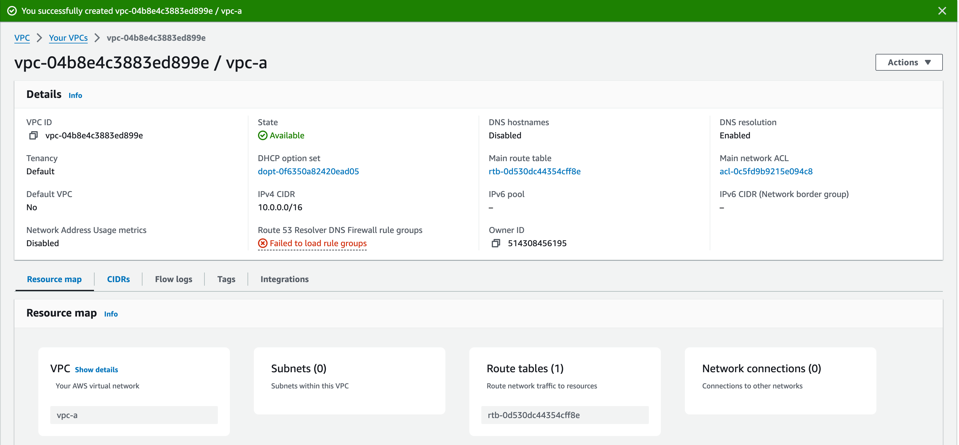
8. Click ‘Create VPC’. This should bring up the details of the VPC you have just created, along with a green banner at the top of the screen. A recently added feature is the ‘Resource Map’, which shows you which resources are associated with your VPC. Currently, we only have the VPC itself and one Route Table. This is the ‘Default Route Table’, which directs traffic locally within the VPC.
9. Click ‘Your VPCs’ from the left pane or the blue link at the top of the screen. You should see ‘vpc-a’. There may be other VPCs too. You can ignore these – they have been created by default with your account.
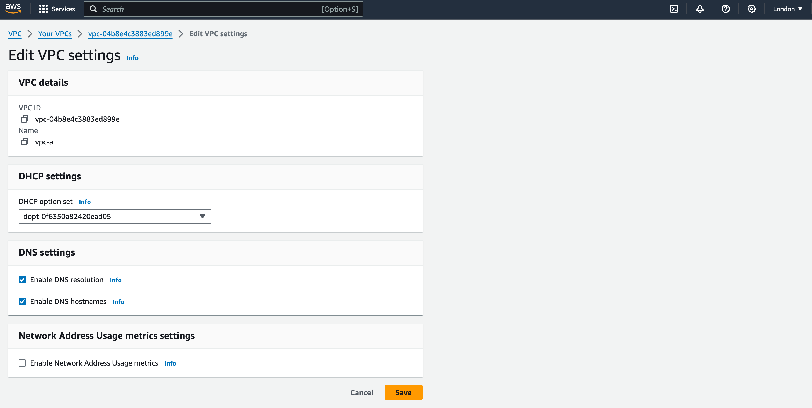
10. We will now edit some of the VPC configuration. Click the ‘Actions’ button in the top-right corner and Select ‘Edit VPC Settings’.
11. Tick the boxes for ‘Enable DNS resolution’ and ‘Enable DNS hostnames’. (this will allow you to connect to your EC2 instances in future sessions).
12. Leave all other settings as default and click ‘save’.
Configuring Public Subnets
- From the left pane, select ‘Subnets’ and then ‘Create Subnet’
2. Select “vpc-a” from the VPC ID drop-down menu
3. Name the subnet as ‘public-subnet-01’, select ‘eu-west-2a’ as the Availability Zone, and add “10.0.1.0/24” as the CIDR Block for this subnet
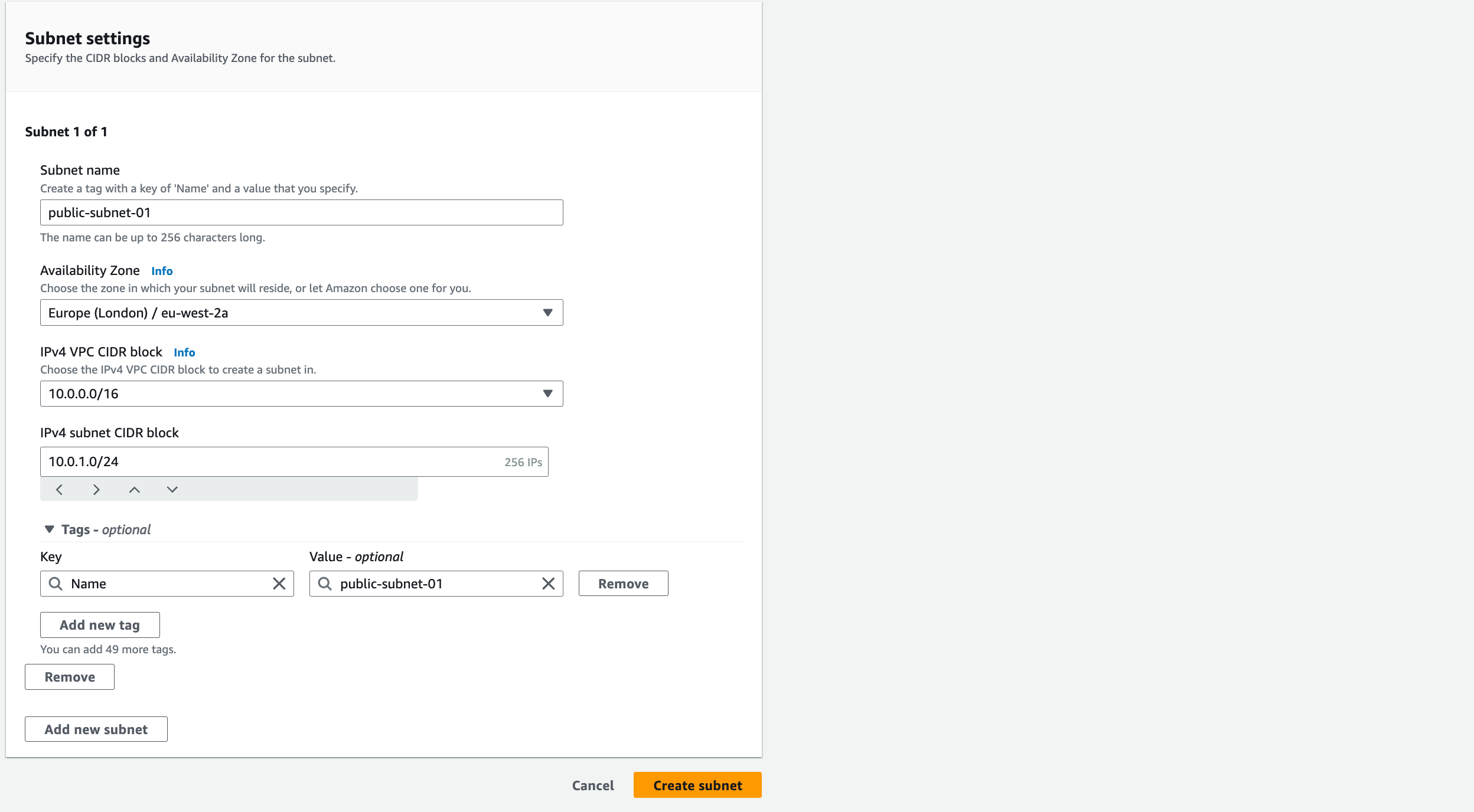
4. Click ‘Add New Subnet’ to add the 2nd Public Subnet
5. Name this as ‘public-subnet-02’, select ‘eu-west-2b’ as the Availability Zone and add ‘10.0.2.0/24’ as the CIDR Block for this subnet
6. Click ‘Create Subnet’ at the bottom of the page
Whilst for the purpose of this workshop we are calling these subnets ‘Public’, they are only actually ‘Public’ after being routed to an Internet Gateway
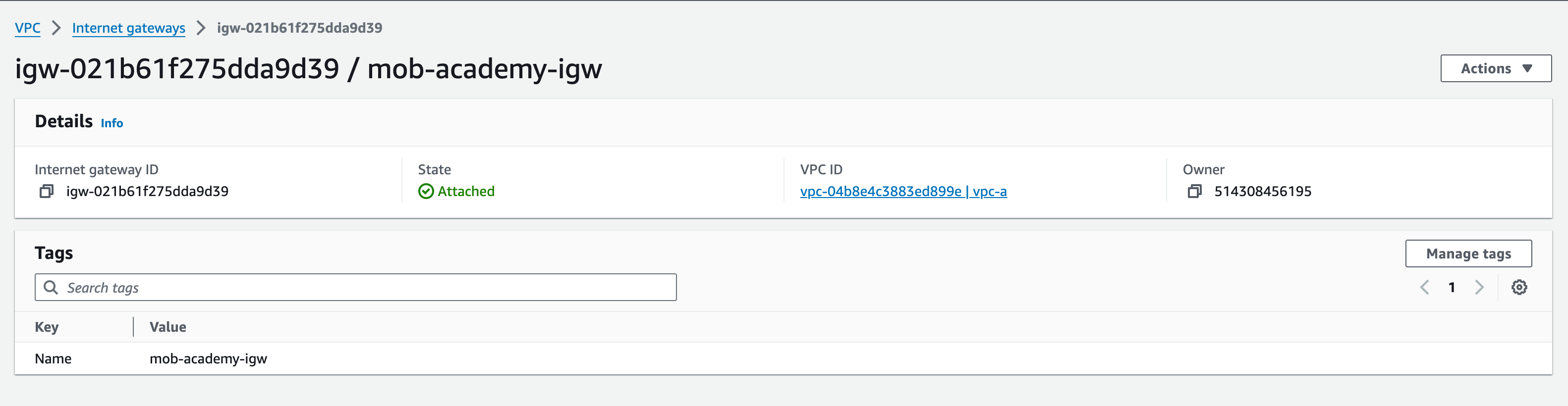
Configuring Internet Gateway
- From the left pane, select Internet Gateways and then “Create Internet Gateway”
- Name the Internet Gateway ‘mob-academy-igw’
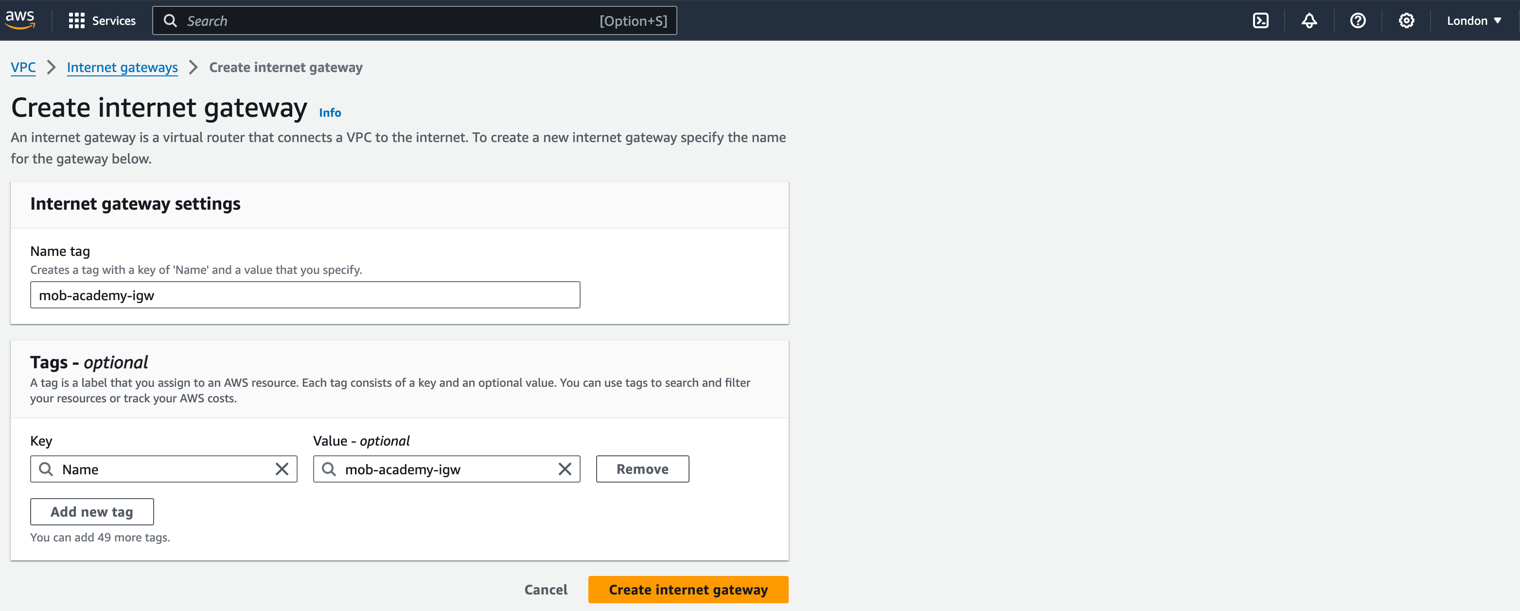
3. Click ‘Create internet gateway’
This should bring up a page showing your internet gateway (IGW) with a ‘success’ message.
4. Next, select the IGW and click the ‘Actions’ drop-down menu, select ‘Attach to VPC’ and select ‘vpc-a’ from the drop-down menu. This will bring up the VPC ID of your vpc-a. Click ‘Attach internet gateway’.
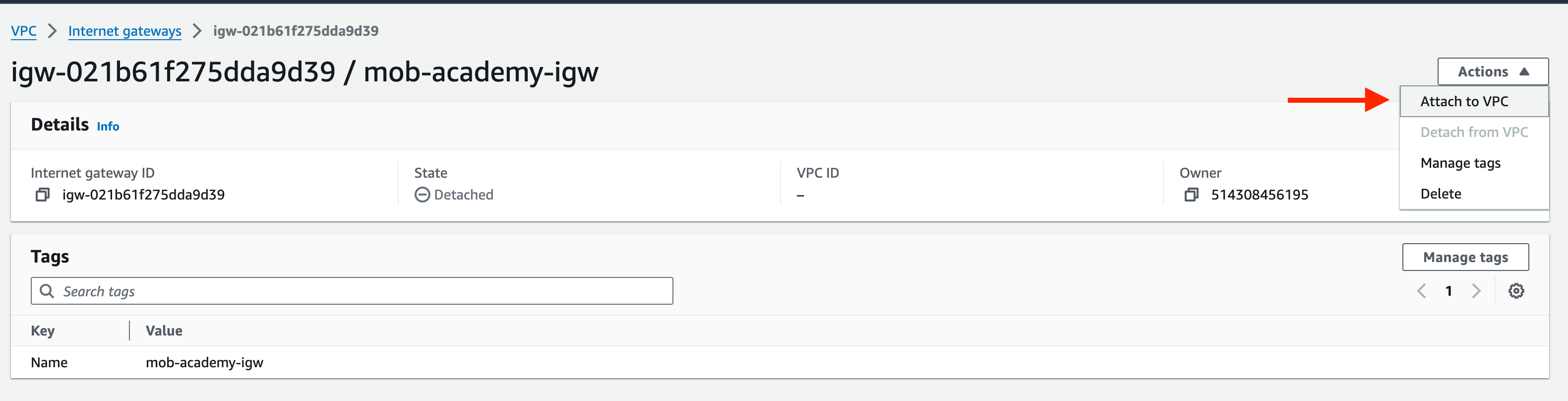
5. Again, you will see the details of your IGW. This time, you should see that the state has changed from ‘Detached’ to ‘Attached’ with a ‘success’ message at the top of the screen.
An IGW is similar to a NAT Gateway (NGW), in allowing outbound connections to the internet, however an IGW allows Inbound connections from the internet, whereas a NGW blocks inbound connections. NGWs are commonly used by resources within Private Subnets, which require internet access for patching, updates, external database connections etc
Configuring NAT Gateways
1. From the left pane, select Elastic IPs and then select “Allocate Elastic IP address”
2. Leave all settings as default
3. Click “Allocate”
4. Make a note of the allocated IPv4 address and Allocation ID
5. Next, select NAT Gateways from the left pane and click “Create NAT Gateway”
6. Name the NGW as “mob-academy-ngw-01”, select “public-subnet-01” from the Subnet dropdown menu
7. Connectivity type: ‘Public’.
8. Select the newly allocated Elastic IP from the Elastic IP allocation ID dropdown menu
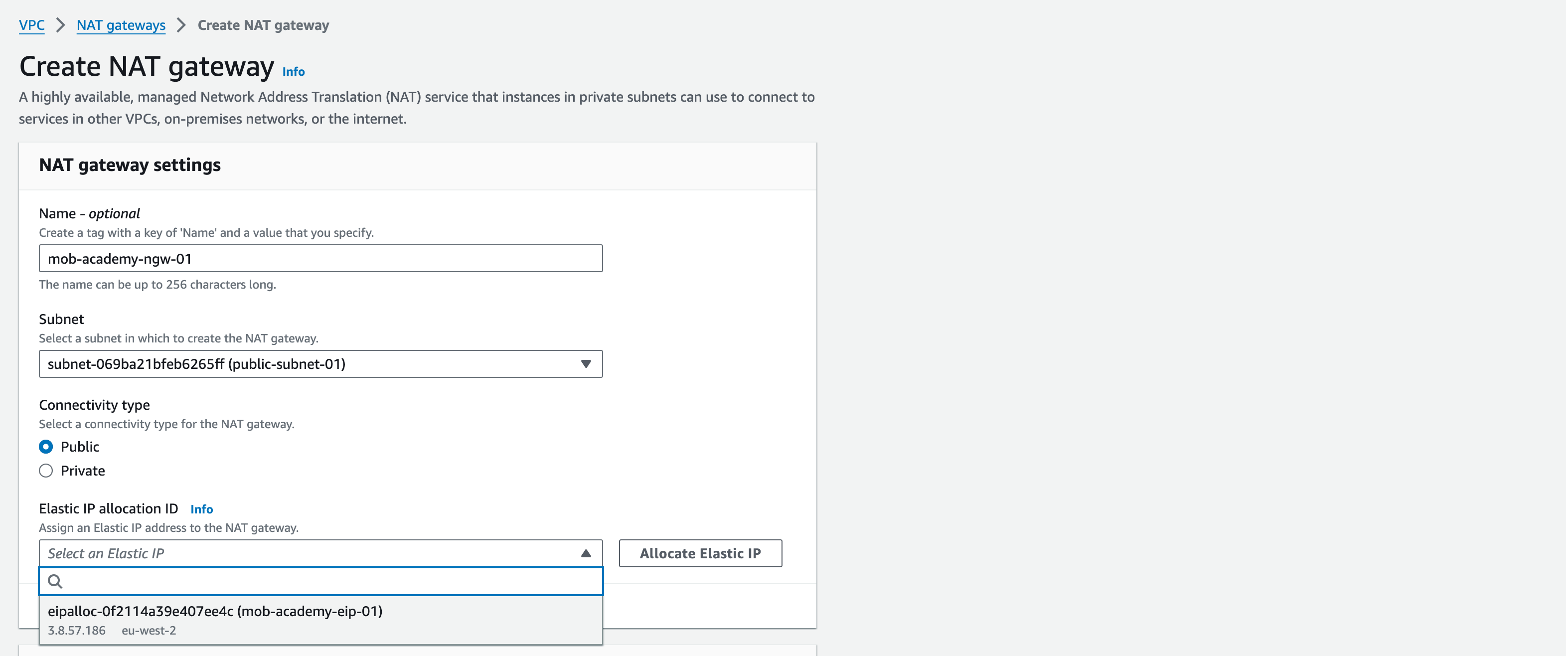
9. Click “Create NAT Gateway” (note – this may take several minutes to create)
10. Repeat steps 1 to 11, changing the name of the NGW in step 7 to ‘mob-academy-ngw-02′ and selecting ‘public-subnet-02′. Name the 2nd Elastic IP ‘mob-academy-eip-02’.
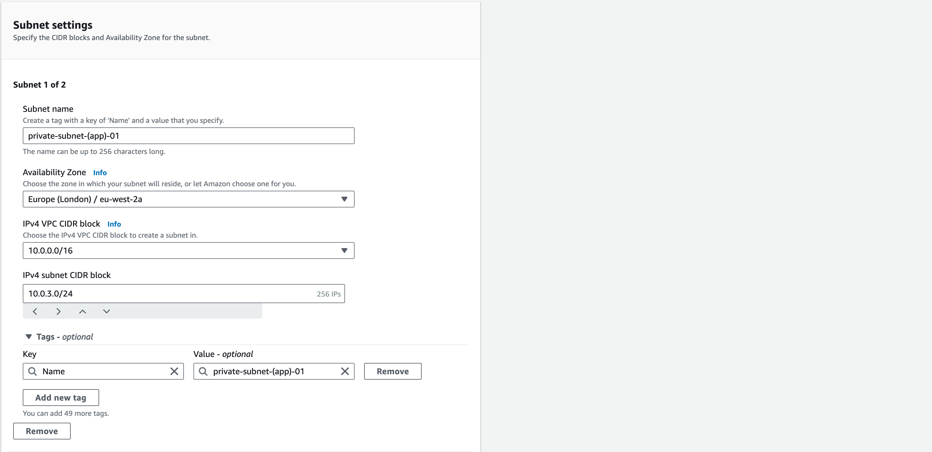
Configuring Private App Subnets
- From the left pane, select Subnets and then “Create Subnet”
- Select “vpc-a” from the VPC ID drop-down menu
- Name the subnet as “private-subnet-(app)-01”, select ‘eu-west-2a’ as the Availability Zone, and add “10.0.3.0/24” as the CIDR Block for this subnet.
- Click “Add New Subnet” to add the 2nd Private Subnet
- Name this as “private-subnet-(app)-02”, select ‘eu-west-2b’ as the Availability Zone and add “10.0.4.0/24” as the CIDR Block for this subnet
- Click “Create Subnet” at the bottom of the page
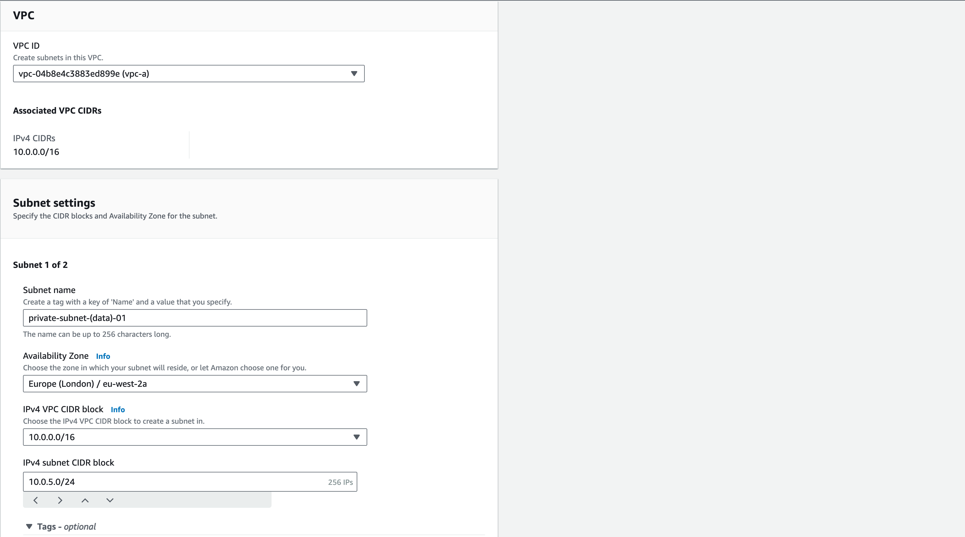
Configuring Private Data Subnets
- From the left pane, select Subnets and then “Create Subnet”
- Select “vpc-a” from the VPC ID drop-down menu
- Rename the subnet as “private-subnet-(data)-01”, select eu-west-2a as the Availability Zone, and add “10.0.5.0/24” as the CIDR Block for this subnet
- Add standard tags
- Click “Add New Subnet” to add the 2nd Private Subnet
- Name this as “private-subnet-(data)-02″
- Select eu-west-2b as the Availability Zone and add “10.0.6.0/24” as the CIDR Block for this subnet
- Click “Create Subnet” at the bottom of the page
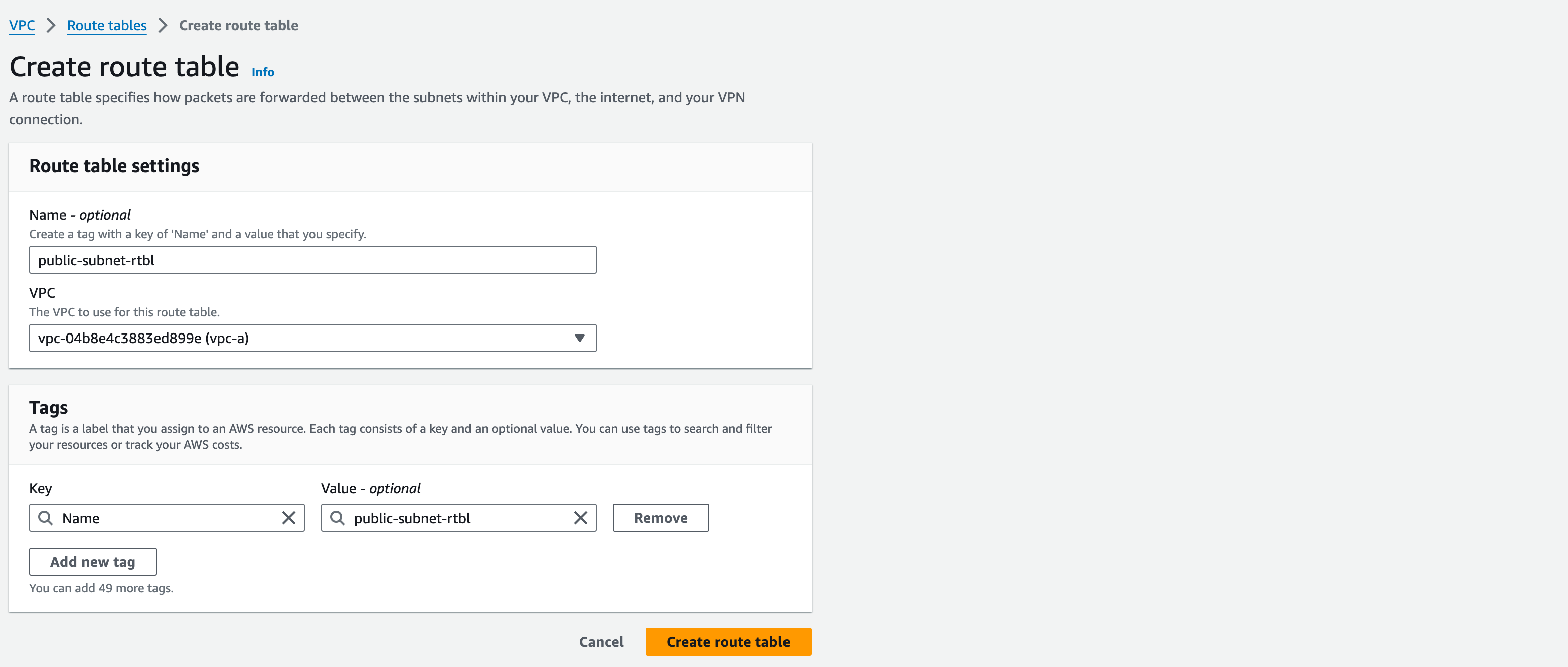
Creating a Public Subnet Route Table
- Still within VPC service, select Route Tables from the left pane
- Click “Create Route Table”, name this Route Table (RT) as “public-subnet-rtbl”, and select “vpc-a” from the dropdown menu”, add standard tags then click “create route table”
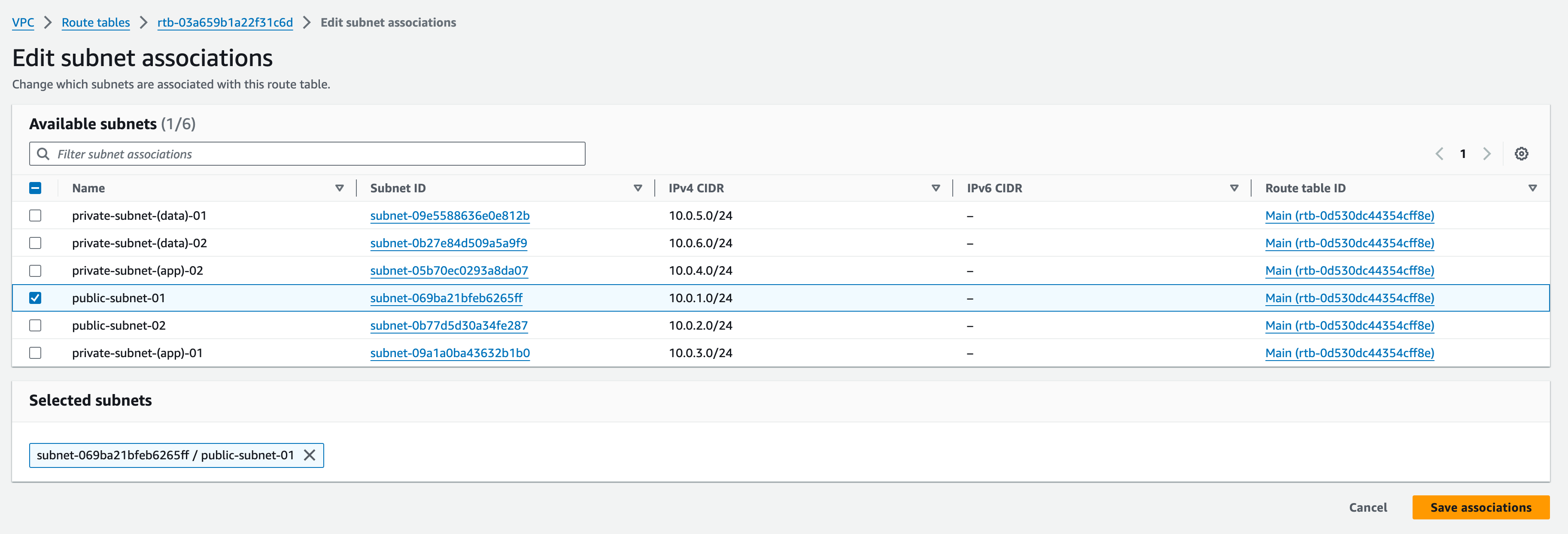
3. Once created, select the RT and then from the Actions button, select “Edit Subnet Associations”; find “public-subnet-01” and then click “Save Associations” at the bottom of the page
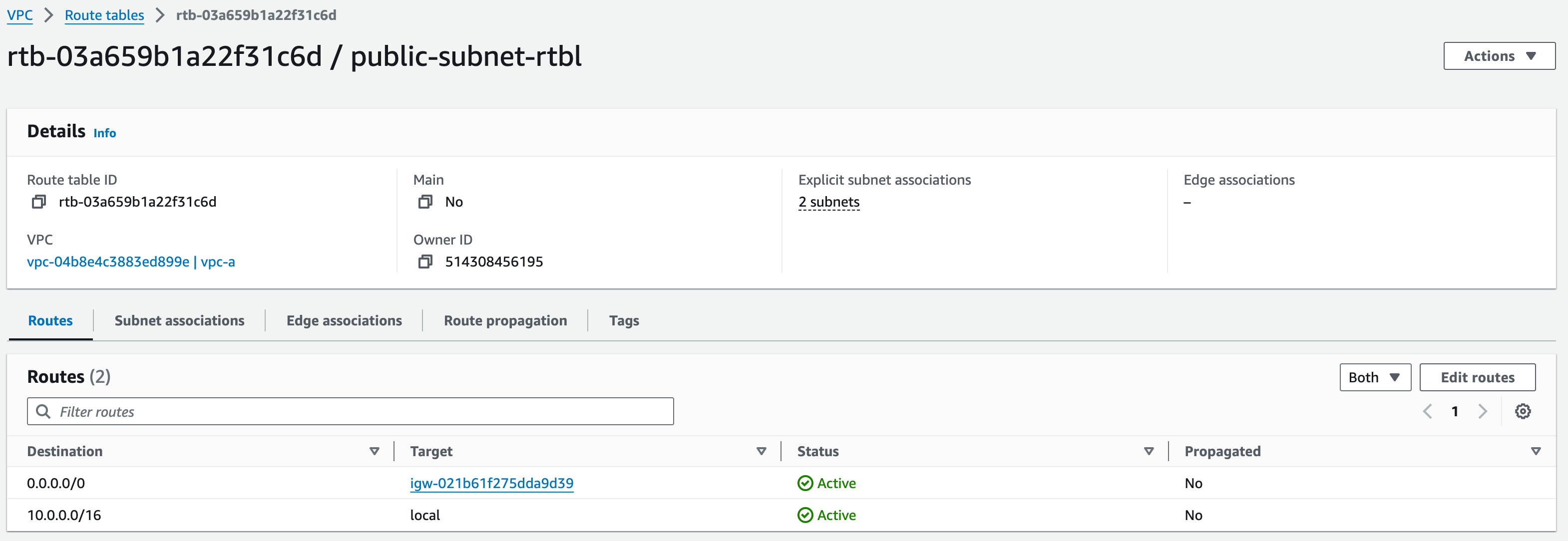
4. Reselect the RT and then from the Actions button, select “Edit routes”
5. By default, there will already be a route with destination “10.0.0.0/16”, with the Target set as ‘Local’; we also need to add a new route to the Internet Gateway.
6. Click “Add route”, set Destination as 0.0.0.0/0, and in Target type “igw-“ (make sure to include the hyphen); which should bring up the created IGW
7. Click ‘save changes’
8. We will also associate “public-subnet-02″ with the same RT. Do this by repeating step 3, associating “public-subnet-02″ and associate it with public-subnet-rtbl.
Creating App Subnet Route Tables
Private Subnet 1:
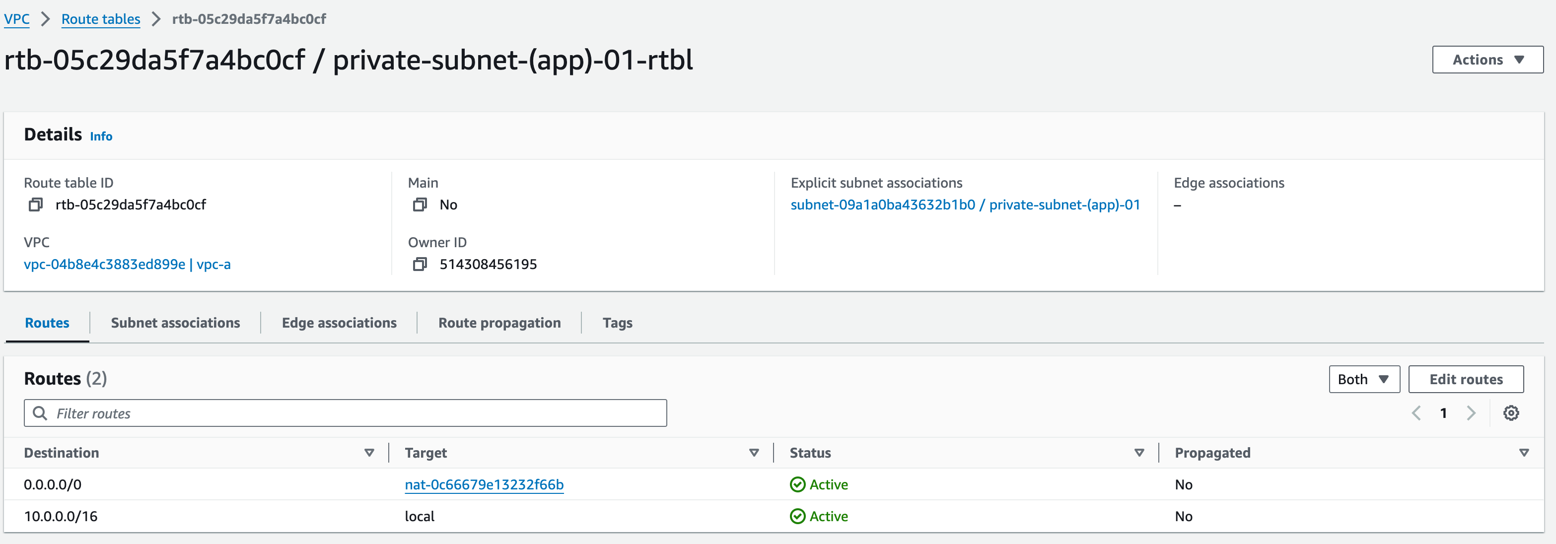
- Click “Create Route Table”, name this Route Table (RT) as “private-subnet-(app)-01-rtbl”, select “vpc-a” from the dropdown menu”, add standard tags and click “create route table”
- Associate this RT with “private-subnet-(app)-01”
- Edit the routes – we need to add a route with Target type “nat-“, (make sure to include the hyphen); click ‘NAT Gateway’, select ‘mob-academy-ngw-01′ and set the Destination as ‘0.0.0.0/0’.
- Click save changes
Private Subnet 2:
Repeat steps 1-4 for ‘private-subnet-(app)-02-rtbl’, selecting the subnet and NAT Gateway in the other availability zone, which are ‘private-subnet-(app)-02’ and ‘mob-academy-ngw-02’ respectively.

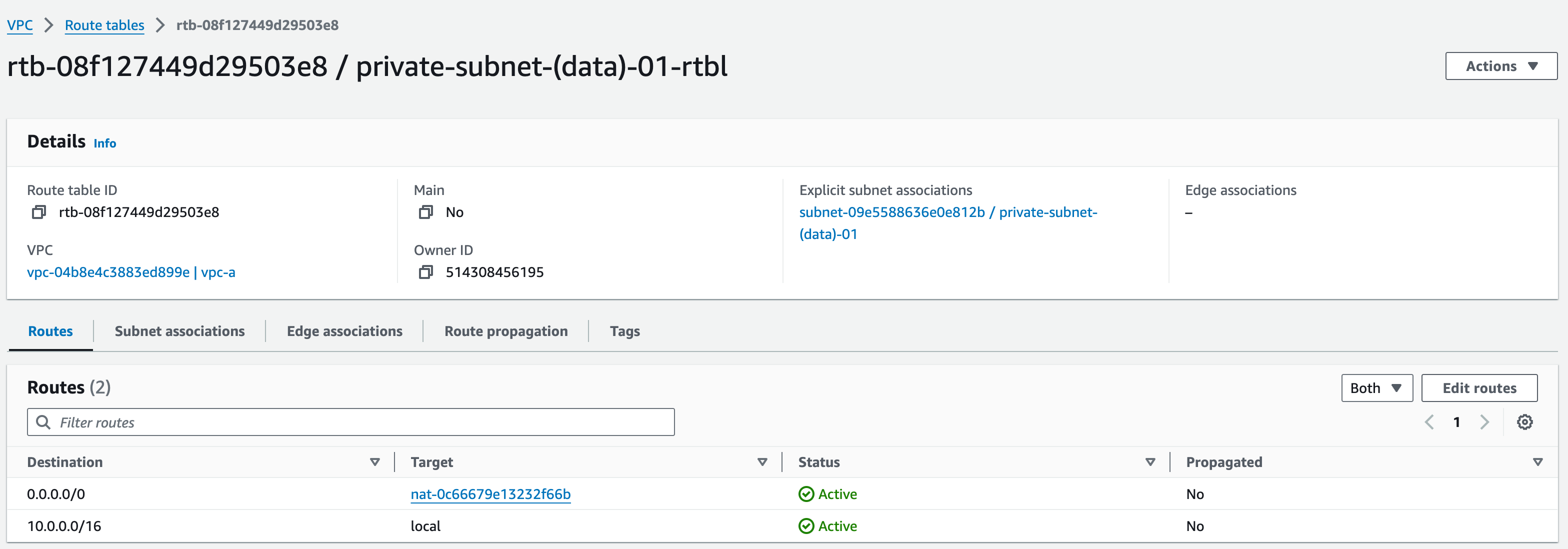
Creating Data Subnet Route Tables
Private (Data) Subnet 1:
- Click “Create Route Table”, name this Route Table (RT) as “private-subnet-(data)-01-rtbl”, select “vpc-a” from the dropdown menu”, add standard tags and click “create route table”
- Associate this RT with “private-subnet-(data)-01”
- Edit the routes – we need to add a route with Target type “nat-“, (make sure to include the hyphen or click in the box); click ‘NAT Gateway’, select ‘mob-academy-ngw-01′ and set the Destination as ‘0.0.0.0/0’.
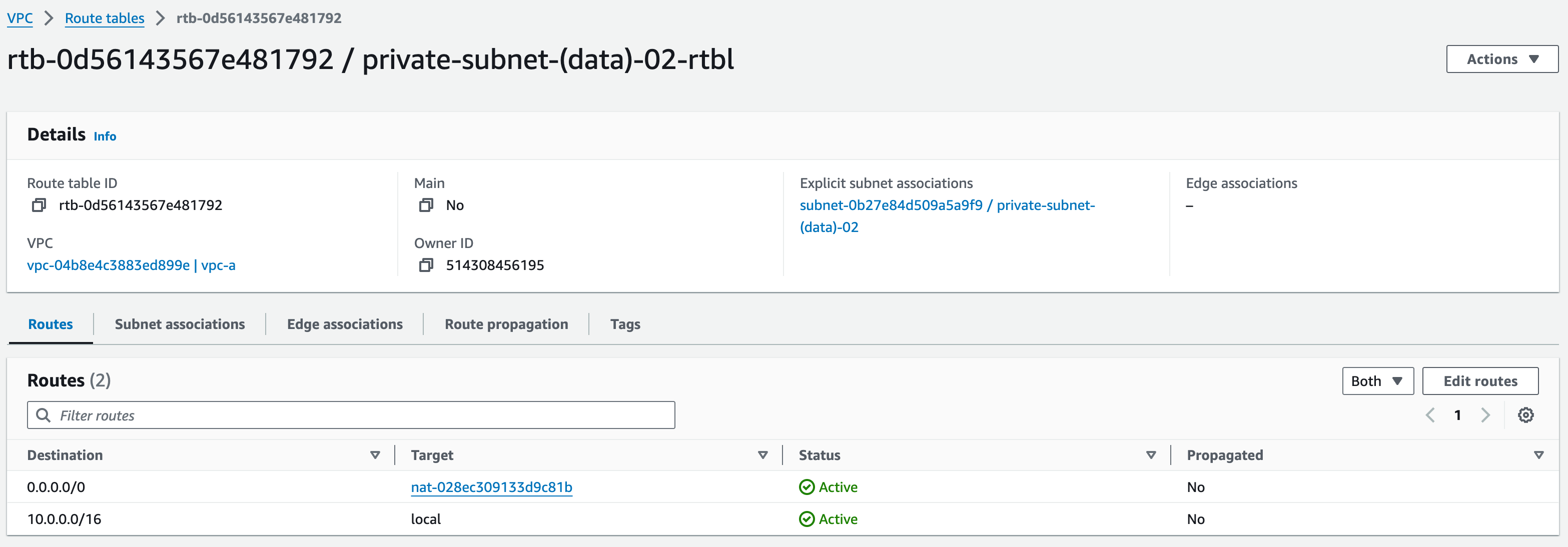
Private (Data) Subnet 2:
Click save changes and repeat steps 1-3 for ‘private-subnet-(data)-02-rtbl’, selecting the subnet and NAT Gateway in the other availability zone, which are ‘private-subnet-(data)-02’ and ‘mob-academy-ngw-02’ respectively.
In this section, we will learn the following:
How to create and configure an Amazon S3 bucket
Default IAM policies and their limitations
Setting up user access, assigning groups and policies
Creating policies for use in the coming sections for different AWS services
Creating S3 bucket
Let’s start by creating our S3 bucket. To create a bucket, navigate to the S3 service in the AWS console and click on “Create bucket”.
Fill in the bucket creation form with the following details:
General configuration
Bucket name: “assets.ma.mobilise.academy”
Replace the ma with your initials
This name needs to be unique as no two buckets in the world can have the same name
AWS region: “Europe (London) eu-west-2”
Object Ownership: “ACLs disabled (recommended)”
Block Public Access settings for this bucket
Untick “Block all public access”
We need users from the internet to access the bucket objects so make sure to untick this box
Tick the acknowledgement box
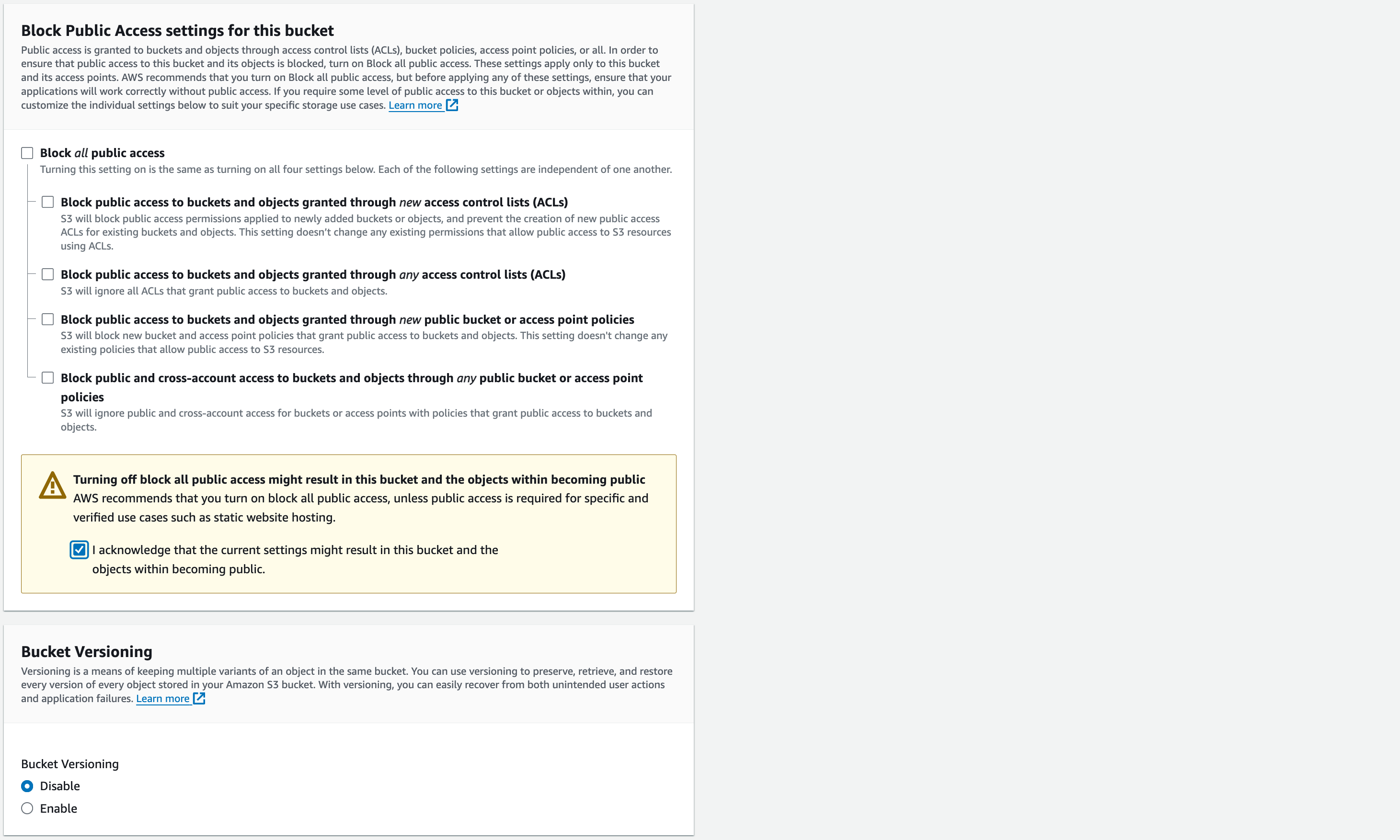
Next, we will enable bucket versioning which you allow for older versions of files to be accessible. For example, if you upload a file that already exists to the bucket the new one will be the default file and you will be able to still access the older versions.
Bucket Versioning: “Enable”
Default encryption
Encryption type: “Server-side encryption with Amazon S3 managed keys (SSE-S3)”
Bucket Key: “Enable”
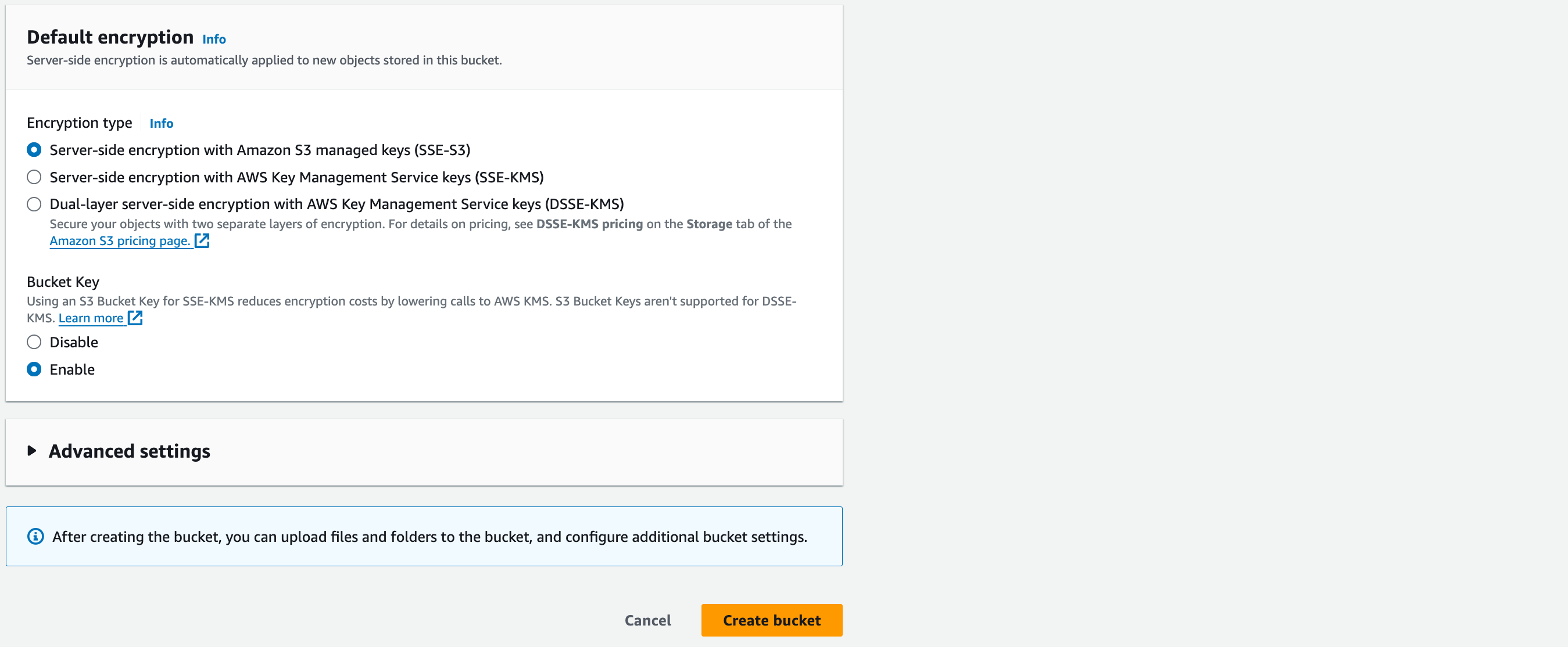
Leave the advanced settings as default and create the bucket.
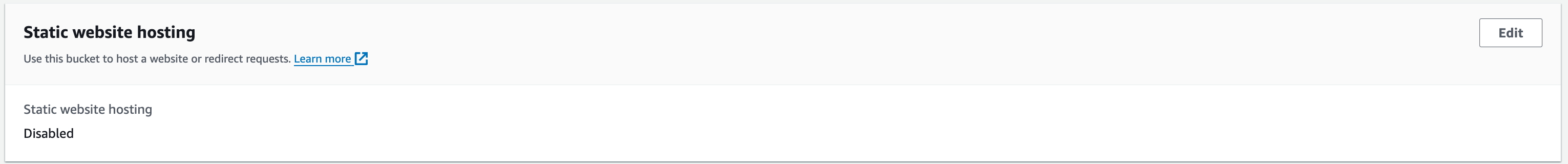
Bucket Static Website Hosting
Next, we will change the static website hosting properties on our bucket, which will set the bucket up for use later in the academy. To set this up, click on the name of the bucket you created in the S3 service, navigate to the “Properties” tab and scroll down to the bottom. Here you will find the “Static website hosting” option. Click the “Edit” button on the right.
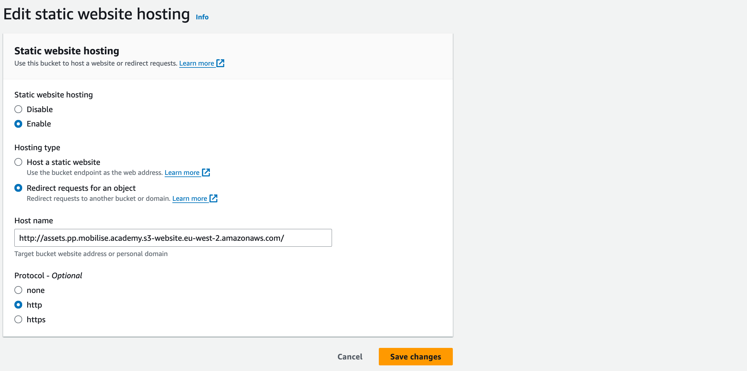
Static website hosting: “Enable” to allow your bucket to start static web hosting.
Hosting type: “Redirect requests for an object”
Host name: http://assets.ma.mobilise.academy.s3-website.eu-west-2.amazonaws.com/
Replace assets.ma.mobilise.academy with the name of your bucket.
Protocol: http
Save changes. You have now set up Static website hosting on your bucket.
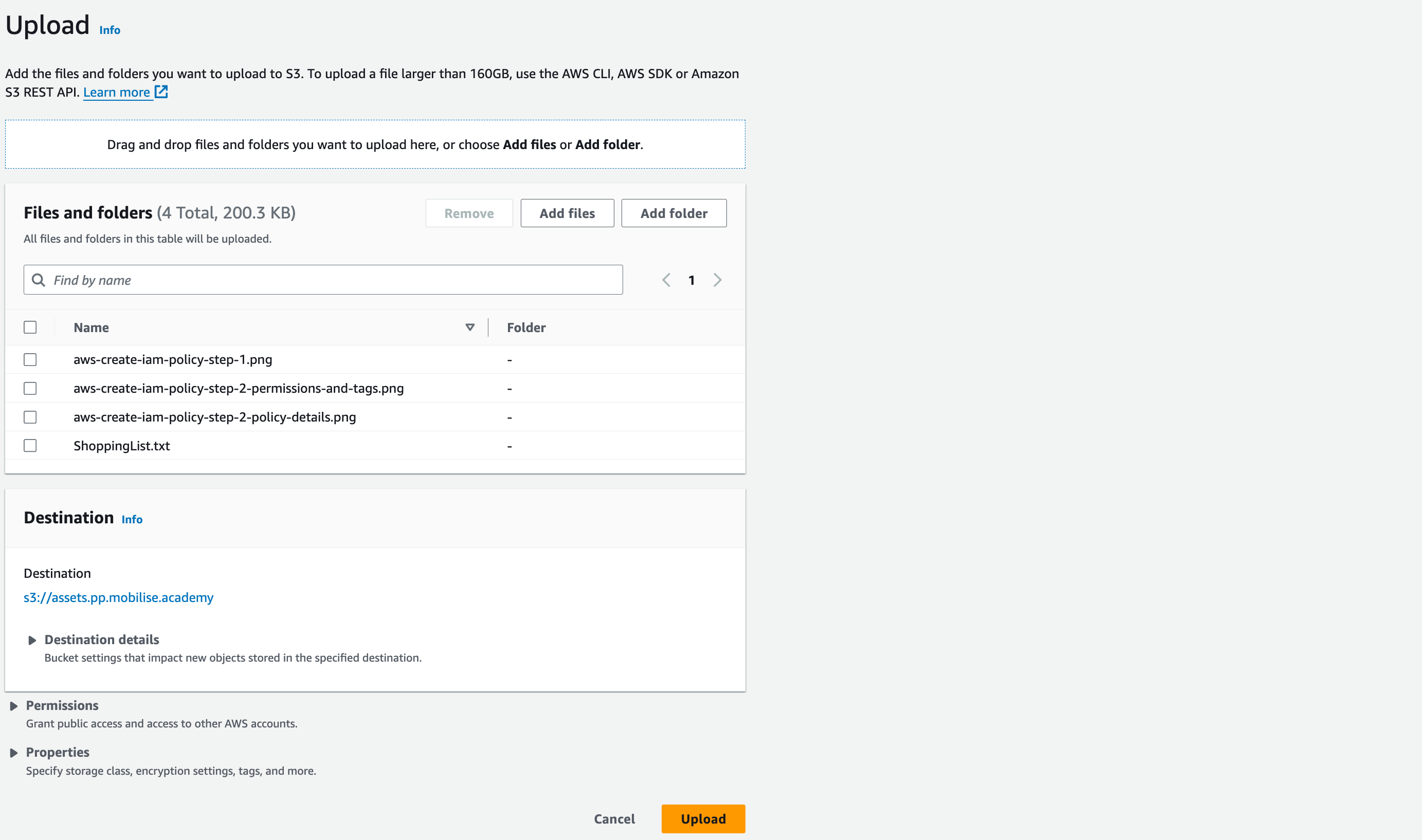
Uploading objects to S3
Let’s upload some files to the S3 bucket you just created. We will use those files in IAM lectures later in this section.
- Download the ZIP file attached to this lecture and extract it.
- Go to your bucket and click the orange “Upload” button. Click “Add files”, locate the folder you extracted from the ZIP file, select all files and click “Upload”.
- Review the “Files and folders” and click the orange “Upload” button at the bottom of the page.
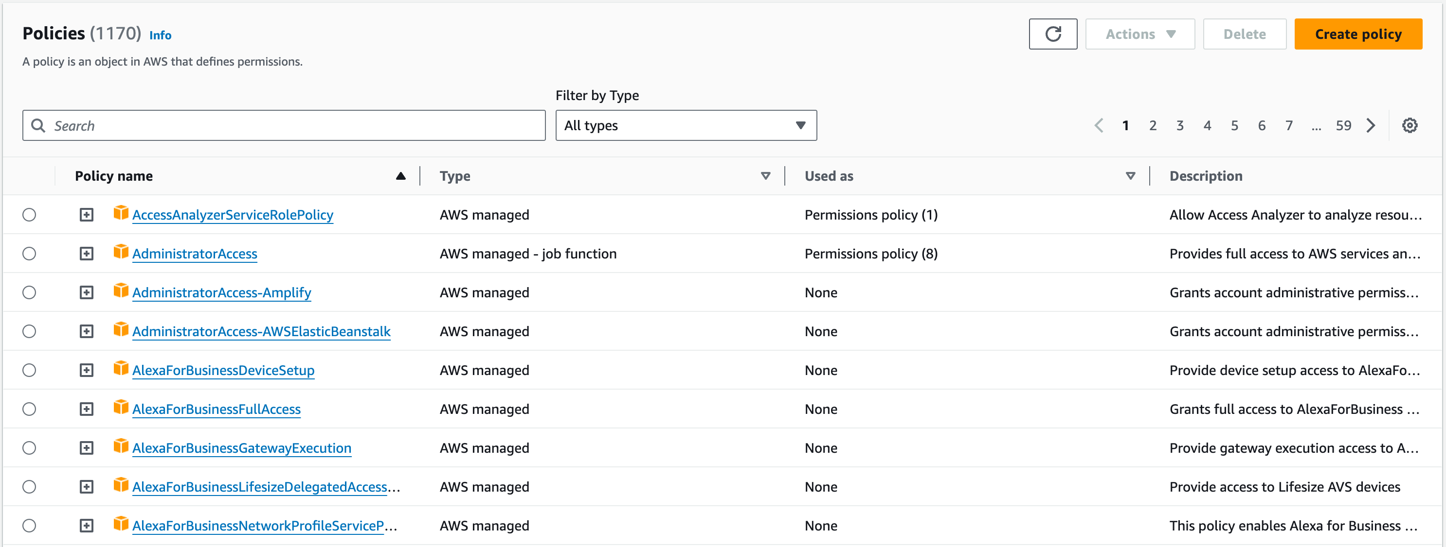
Creating IAM Policies
Now, we will create the “Stop Object Deletion” policy in the AWS console.
There are two ways in which you can create a policy, one being through JSON, as seen in the examples in the previous lecture, or we can use the Visual Editor, which will allow us to create the JSON file through a graphical interface. For this workshop, we shall use the latter.
Navigate to the IAM service, select Policies, and click the orange “Create policy” button in the top right.
To start, select the S3 service in the “Choose a service” dropdown. We want to stop the deletion of an object, so change the Effect from “Allow” to “Deny” and select the DeleteObject action, which is under the Write access level.
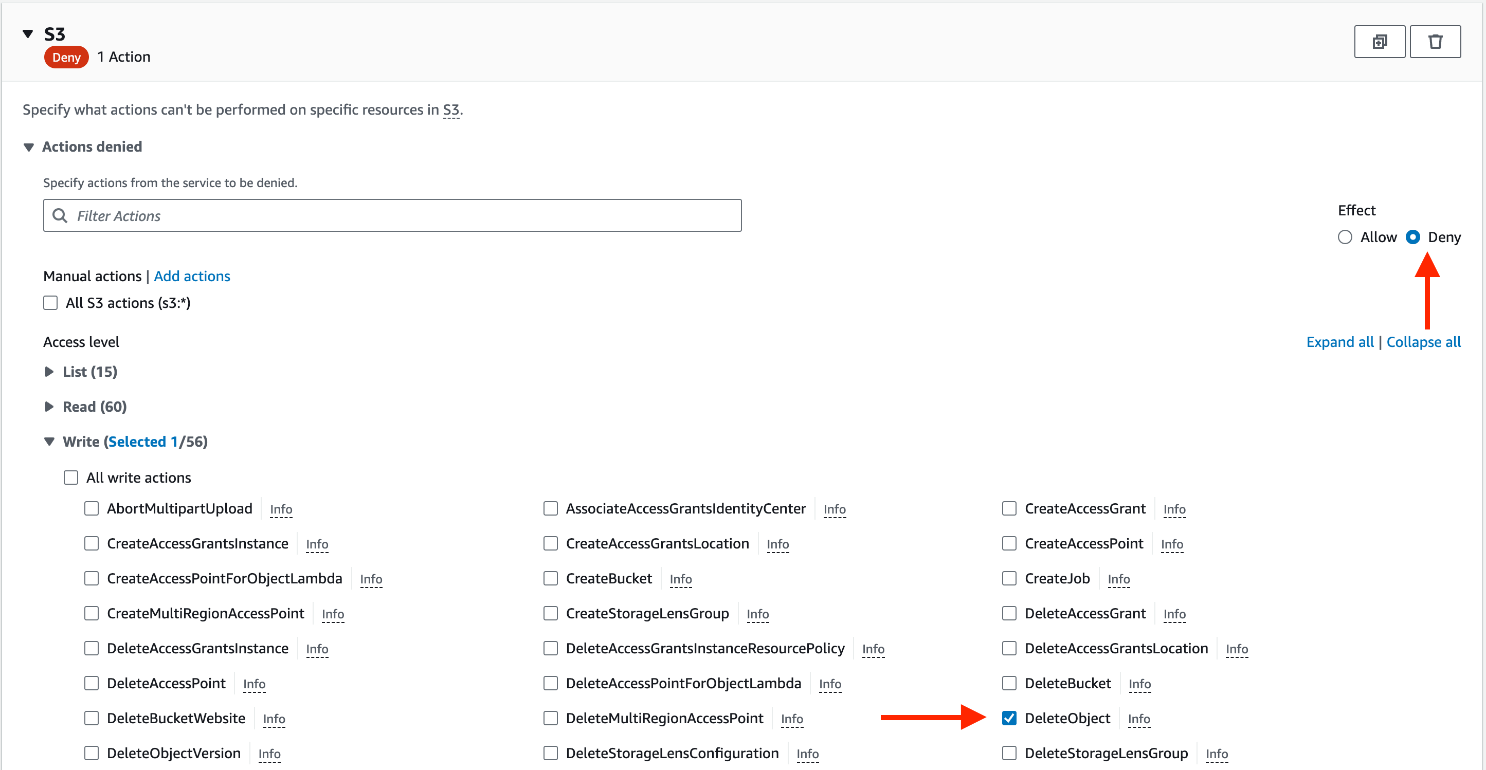
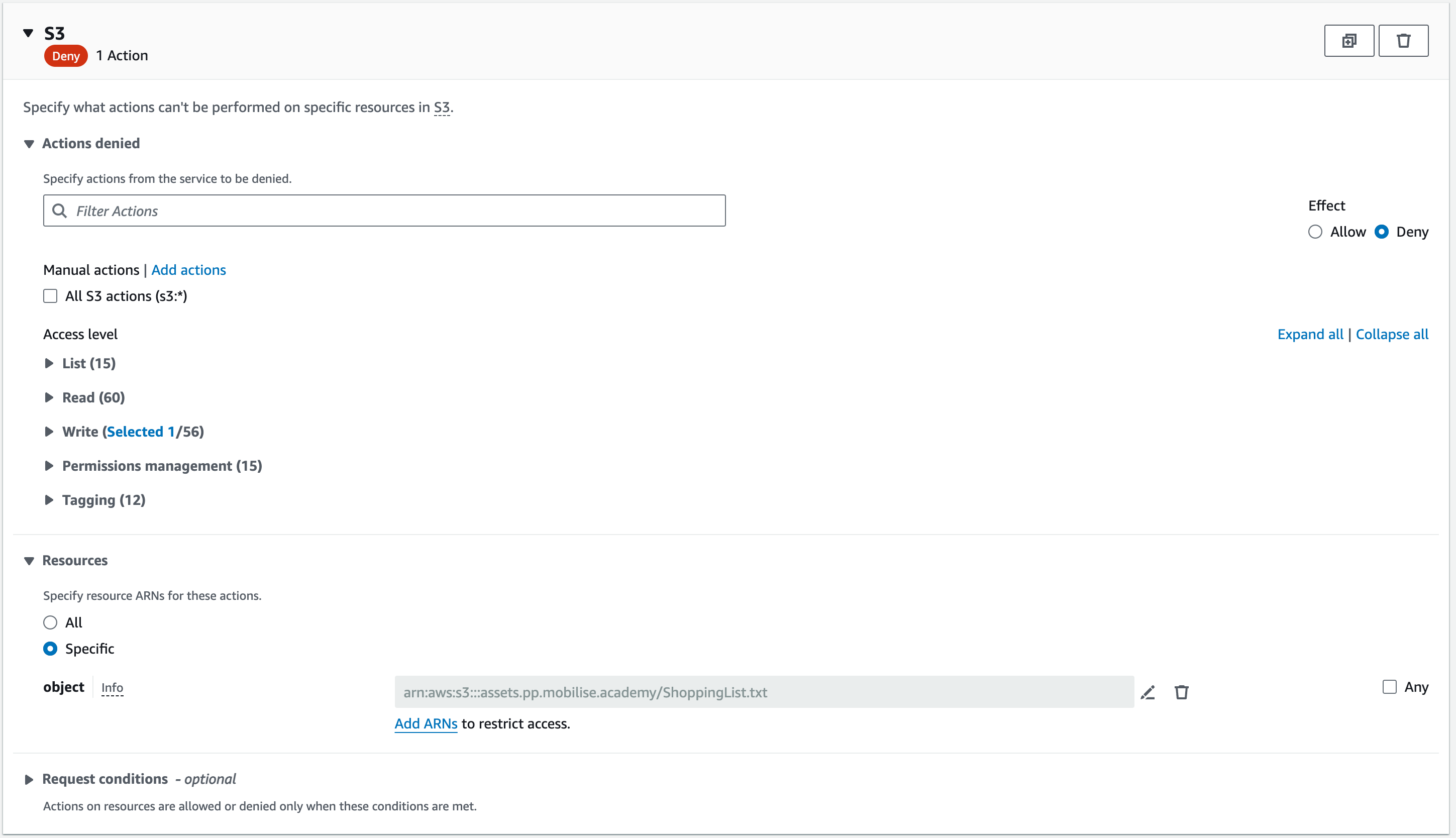
Now, we want to limit the policy to just one resource. To do so, select specific in the resources section and then go and add the name of the bucket you created earlier and add the object inside that bucket.
Once done, you should have something like the screenshot below, with the only difference being your bucket name and object.
On the next page, review everything you have configured and give the policy a name and description.
It is best practice to name the policy in a way that sums up its contents to make it easier when searching through a list of policies and then give it a more detailed description in the description field.
For the name, you can use workshop-s3-deny-delete or create something similar yourself. In the description, put the name of the object you are preventing the deletion of and the name of the bucket.
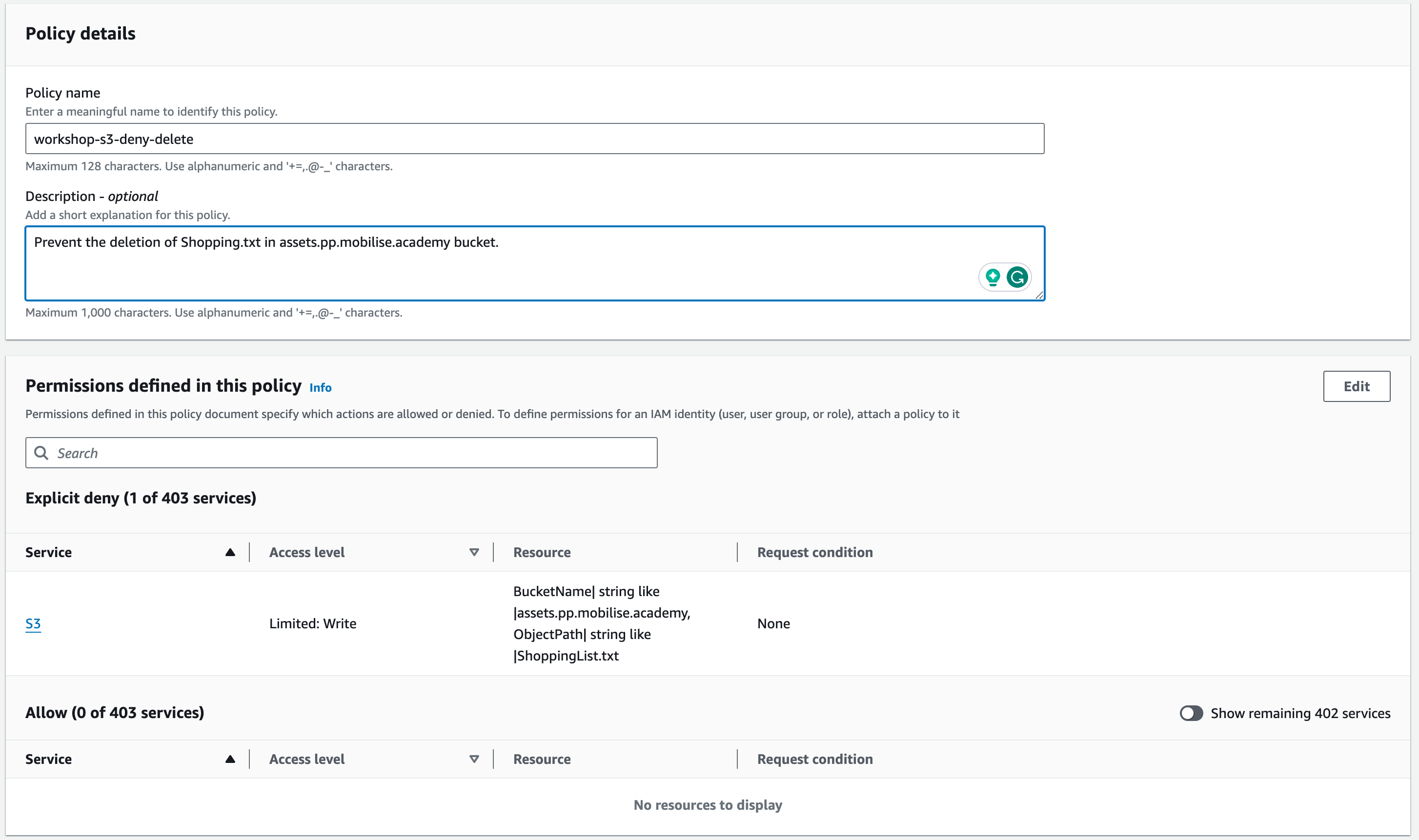
You can now create the policy, and we will attach it to a user in the next part of this section.
Setting Up User Access
To access the AWS console, you need to have a user account. This user needs to have permissions that can be granted either by directly attaching policies to users or by inheritance from the group they are in. In this section, we will create a user, create a group, and attach policies to both the group and the user.
When you create a user in AWS, you can decide if you want to give it programmatic access, which provides the user with an access key and a secret key, or console access, which provides the user with a password that the user can use to log into AWS.
Programmatic access is for accessing AWS via applications and the command line to access AWS APIs.
Creating a User
To start, you will need to access the Users page inside IAM. There, you will click on the orange “Create user” button in the top right.
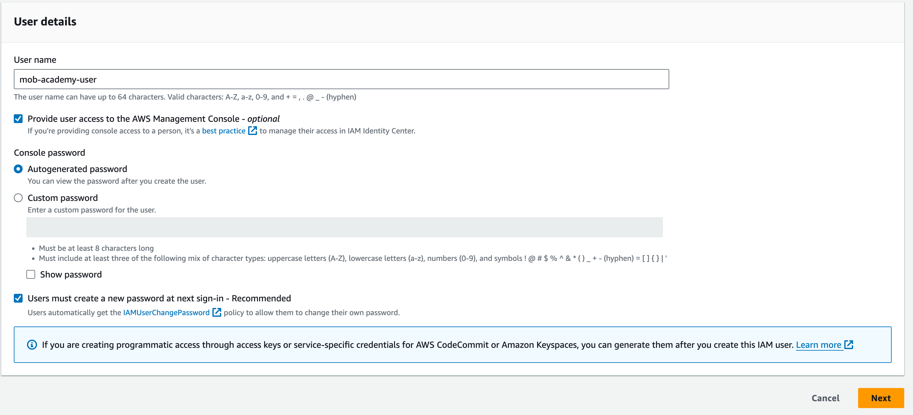
Fill in the information about the user:
User name: mob-academy-user
Tick “Provide user access to the AWS Management Console – optional“
Console password: “Autogenerated password”
Tick: “Users must create a new password at next sign-in – Recommended”
On the next page, we will attach a policy to this user. We will use the AWS Managed policy AmazonS3FullAccess.
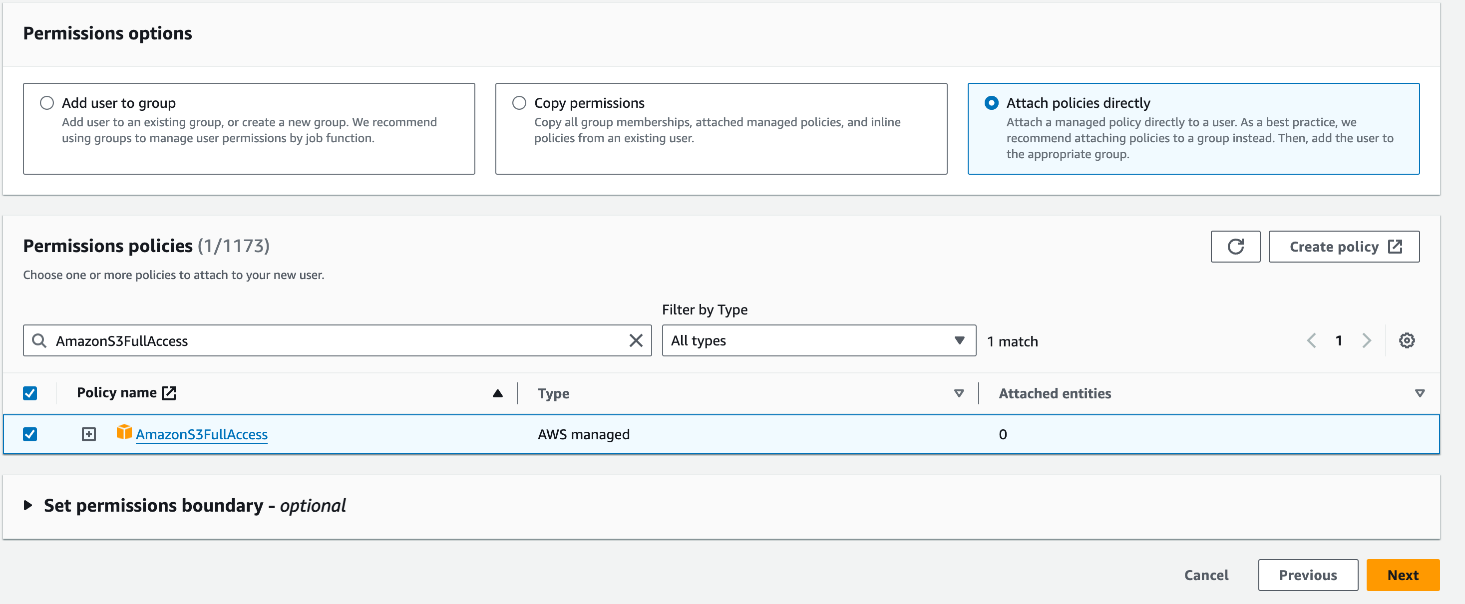
Click “Next” and review the User details and Permissions summary. You should see “IAMUserChangePassword” alongside the “AmazonS3FullAccess”, which grants the user the necessary permissions to change the password.
Click the “Create user” button and download the CSV file with the sign-in details.
Creating and Assigning IAM Groups
Groups are an efficient method of adding permission sets to multiple users. When it comes to AWS, not everyone needs access to the same resources, and the best way to split out permissions is with the use of groups. For instance, we may have a finance department that needs access to only billing and a database team that only needs access to the databases. These teams may have multiple members, and instead of adding permissions individually, we can add the permissions to the group and then add the users to those groups.
That also means that should we need to edit the permissions for these users we can do it for all of them in one go by editing the policy attached to the group. A user can be attached to multiple groups at once.
Creating a Group
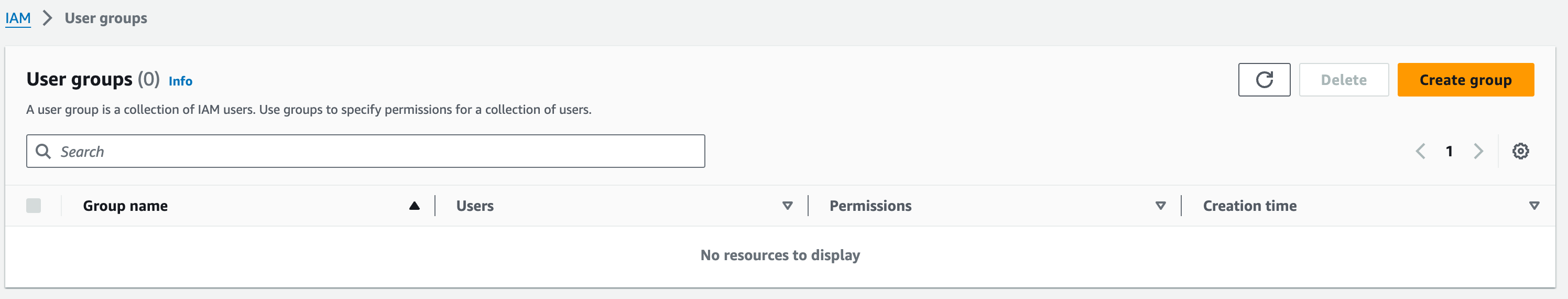
In the IAM service, you will see User Groups on the left-hand side of the page. Click on it and then click the orange button in the top right that says “Create group”.
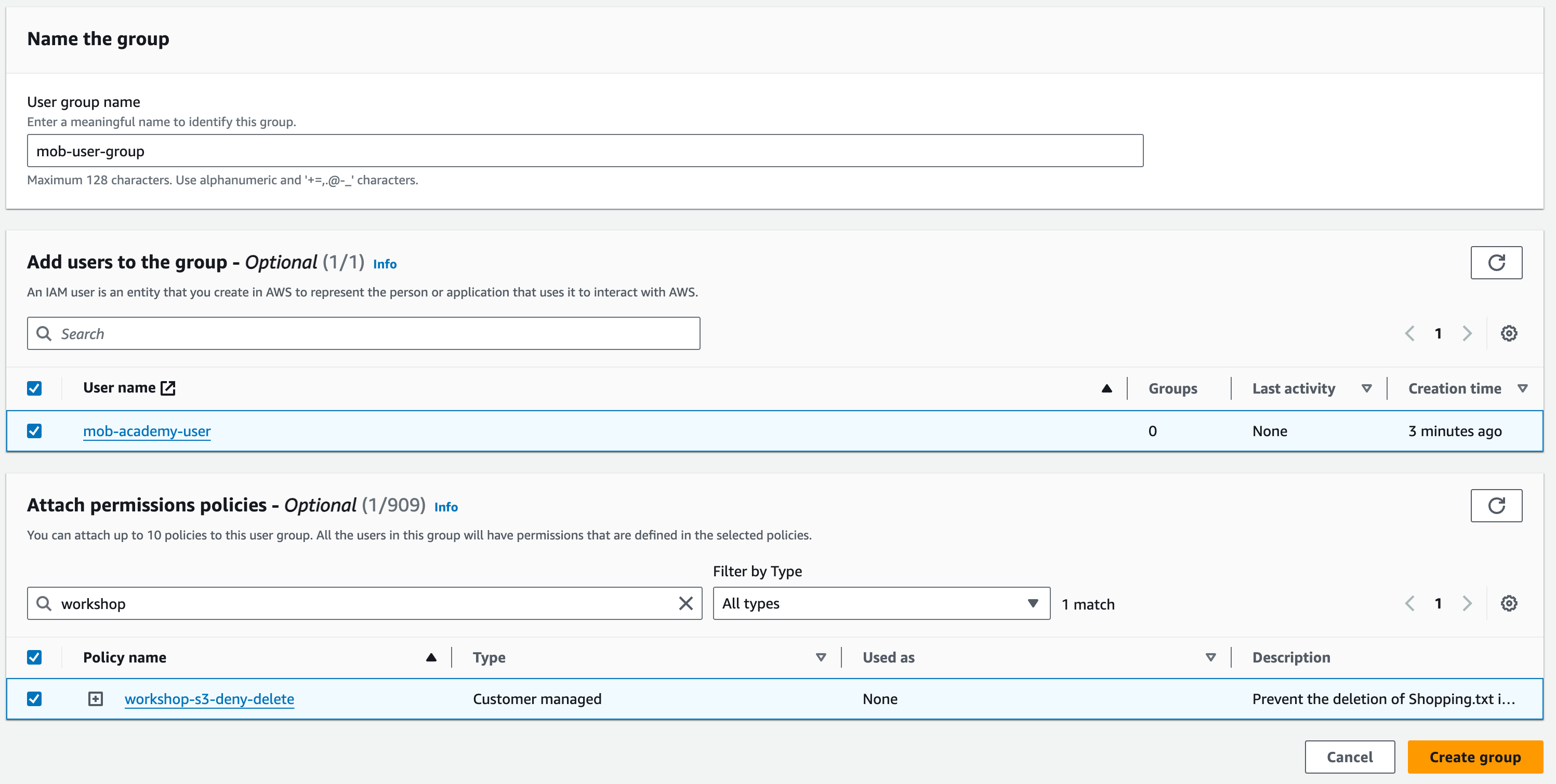
The first step is to give this group a name. It can be whatever you want it to be, but remember, giving it a name relevant to its purpose will make life easier for yourself and everyone else down the line.
The next step is to select the user that you want to add to the group. Select the user that you created earlier. Then, you need to add a policy and choose the one we made earlier that blocks the object deletion in S3.
You should see something similar to the screenshot below. If so, hit the “Create group” button.
Now that you have added the user to the group, we can check what permissions the user now has. Navigate to the user you created, and then you should see the permissions we added to the user and the permissions attached from the group.
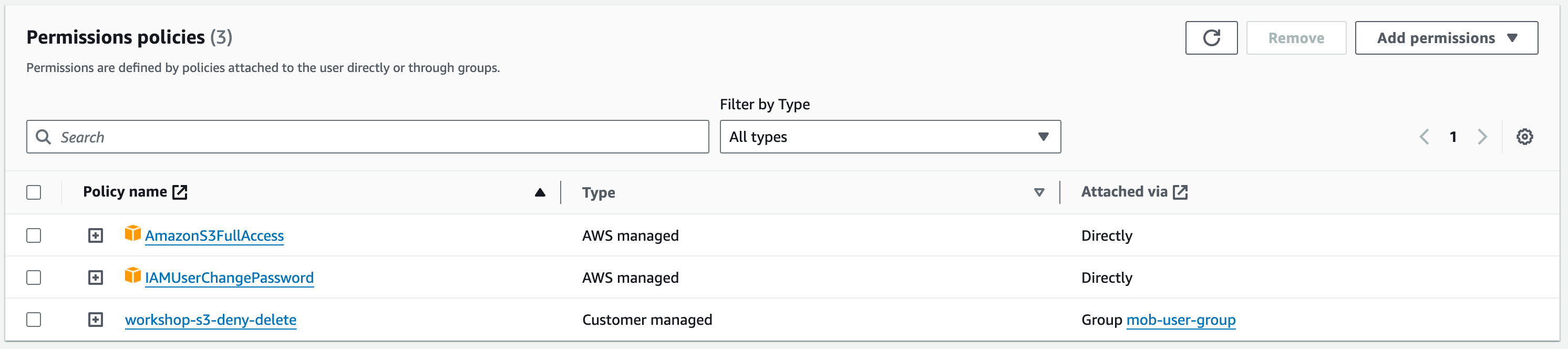
Note that this user now has got two conflicting policies. The policy attached to the user allows all actions on any S3 bucket and object, but the policy attached from the group prevents an object deletion.
The presence of the group policy will prevent the user from deleting the file even with the policy allowing them access to delete. The reason for this is that the ‘Deny’ will cancel out the ‘user attached policy’. The user can still delete other objects because an explicit deny has not been declared.
IAM Roles
Within AWS, it is not just users interacting with services. Services also interact with other services. Good security practice is to ensure that services have only the access permissions they need, and nothing more. This follows the ‘principle of least privilege’ (see https://docs.aws.amazon.com/IAM/latest/UserGuide/best-practices.html). For example, if we have an EC2 that we want to communicate with an RDS instance, then we will create an IAM role to allow that, and we can limit the actions to only allow the EC2 to read from the database and not make any changes.
Creating an IAM Role
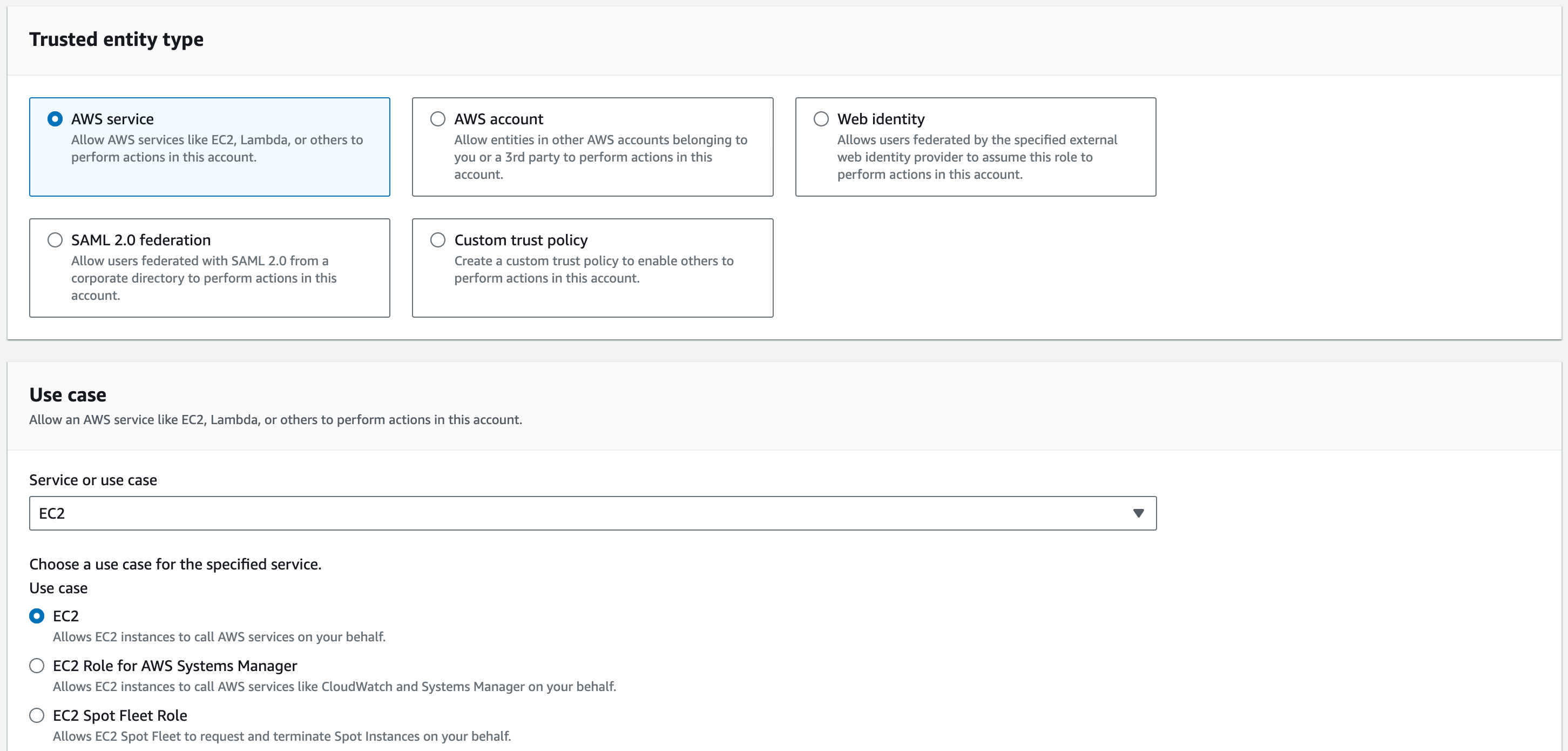
In the IAM service, click “Roles” on the left-hand pane, then click the orange “Create role” button in the top right.
The first thing you will need to do is select the trusted entity type. We are going to be creating a role for an EC2, which is a service provided by AWS. Therefore, we will choose “AWS service”. Choose “EC2” for the Use case and click “Next”.
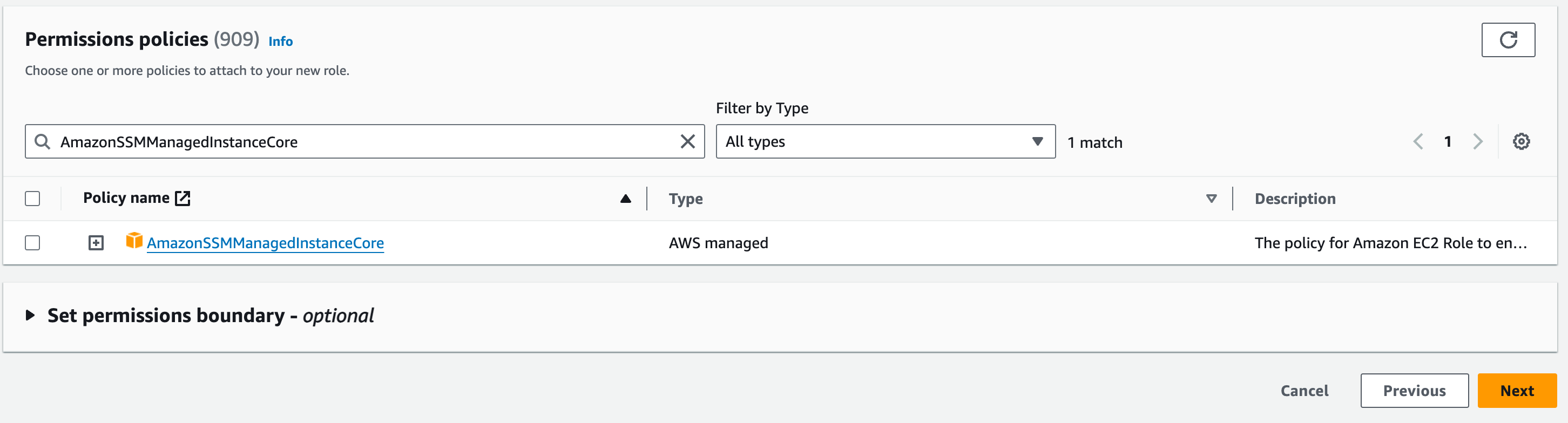
On the next page, we will attach the AWS managed policy “AmazonSSMManagedInstanceCore”. In the search bar, Search for “SSM” and tick the box next to “AmazonSSMManagedInstanceCore”.
Next, we need to provide a name for the role and a description. For the name you can use instance-iam-role and leave the Description as it is.
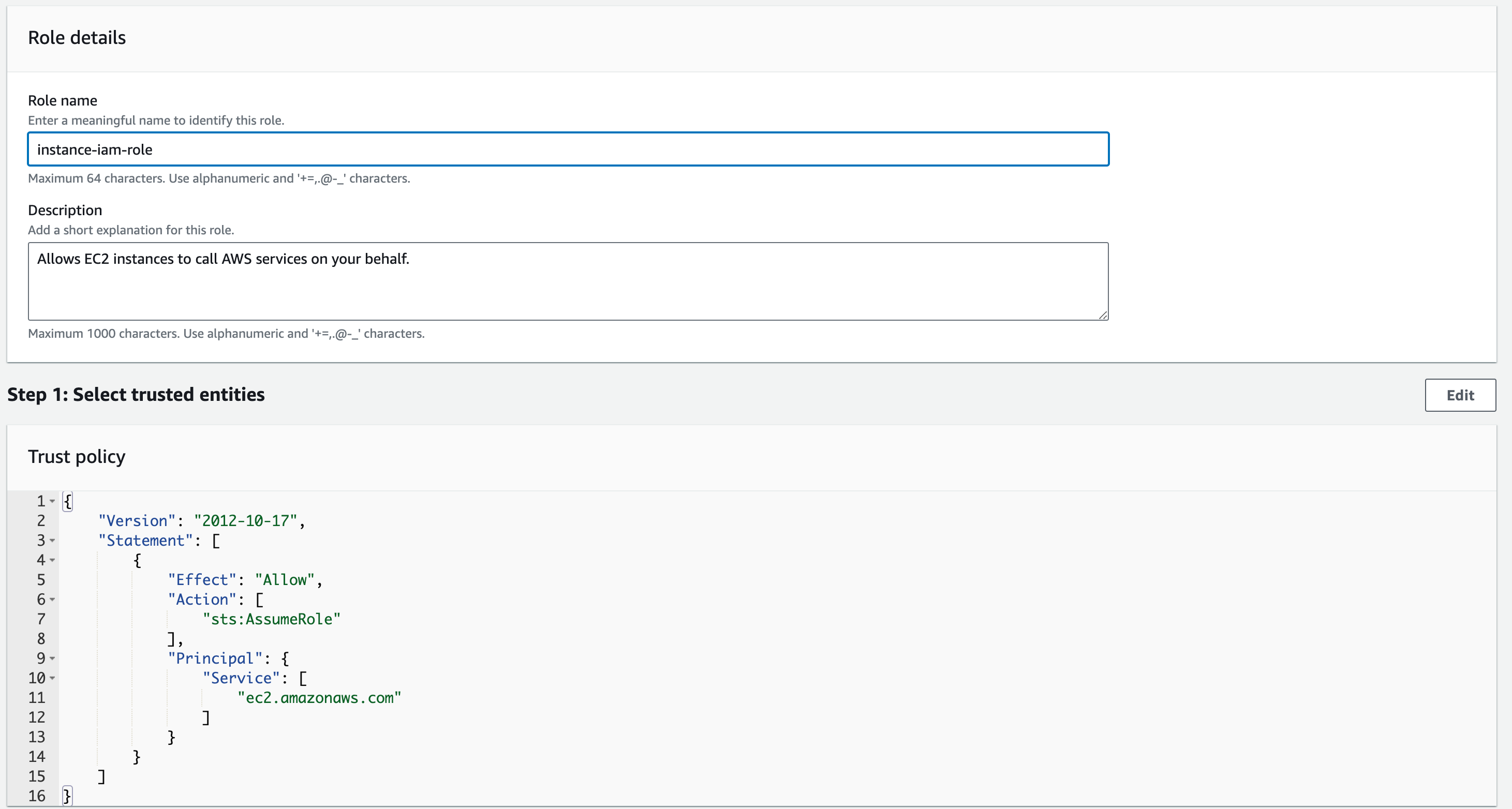
Once done, click “Create role”. For now, we will not use it, but it will come into use later in the section.
Bucket Policy
Now that we learned about IAM Policies, it is time to revisit our S3 bucket.
We will need to add a bucket policy allowing users on the Internet to access the objects in the bucket. To add a policy, go to the bucket you created in the S3 service and navigate to the Permissions tab. Here, find the Bucket policy and click the “Edit” button.
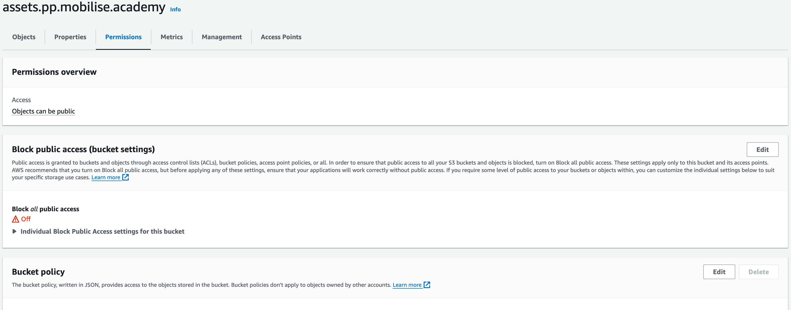
You will now need to add the below policy – copy and paste it in – but change assets.pp.mobilise.academy to the name of the bucket you just created.
- {
- “Version”: “2012-10-17”,
- “Statement”: [
- {
- “Sid”: “PublicReadGetObject”,
- “Principal”: “*”,
- “Effect”: “Allow”,
- “Action”: [
- “s3:GetObject”
- ],
- “Resource”: [
- “arn:aws:s3:::assets.pp.mobilise.academy/*”
- ]
- }
- ]
- }
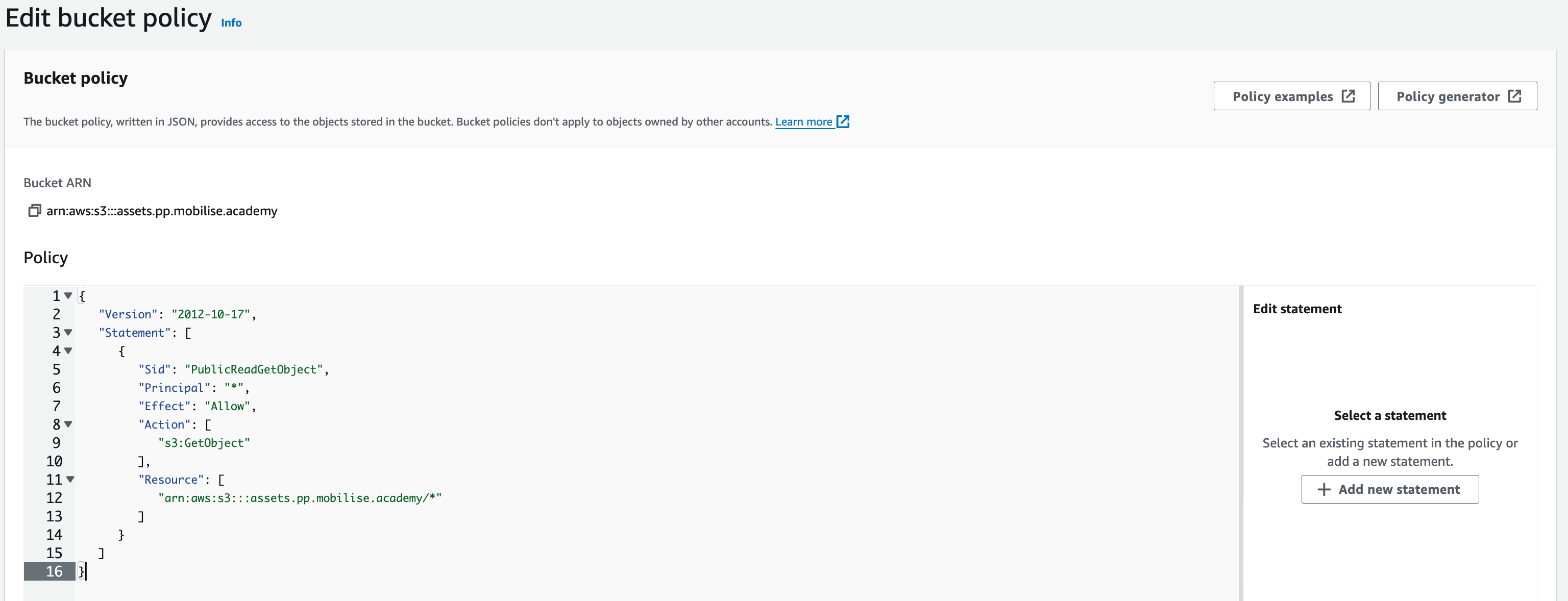
Once done, hit “Save changes”. You have now allowed users on the Internet to access Objects in the bucket. Due to the actions that we have put into the policy, users will only be able to pull (download) the Objects and not upload or edit them.
The objective for this section is to deploy an Amazon RDS Instance: the database that will connect to the WordPress EC2 instance that will we deploy next section. We’ll also deploy Memcached for caching data that supports both our application and database. Lastly, we’ll deploy an Amazon Elastic File System (EFS) for storing data. We’ll also modify WordPress to use these data sources.
The part of the architecture we’ll be deploying this section is highlighted in red.
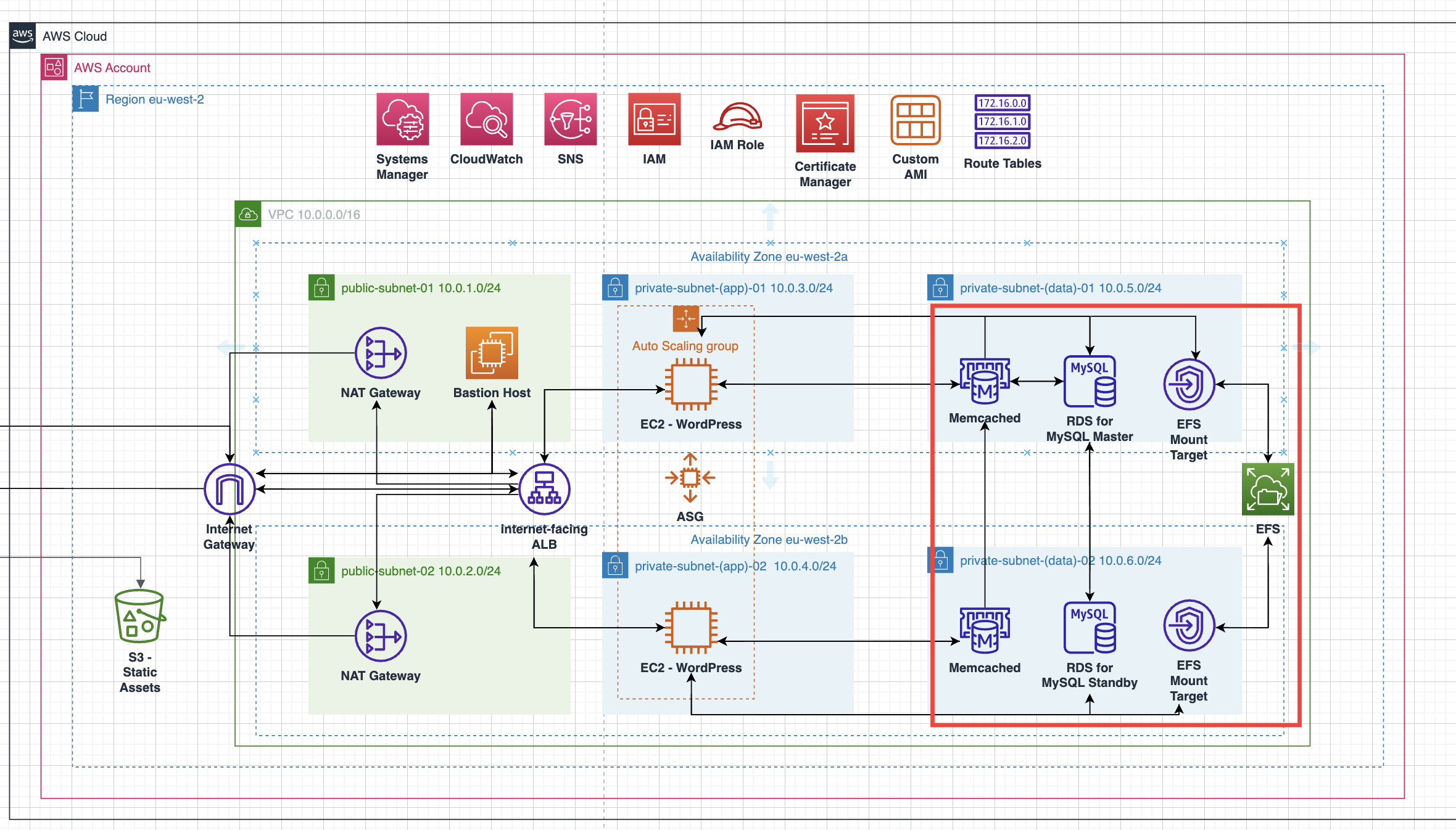
Amazon RDS
Why use Amazon RDS for your WordPress database?
Many installation guides for WordPress use a MySQL database that is on the same server as the WordPress installation. While this may be sufficient to start, there are a number of reasons you may not want your MySQL database on the same server as your WordPress installation.
MySQL and WordPress will be competing for compute resources on the same server, potentially hurting your site’s performance.
You are unable to horizontally scale WordPress by adding additional WordPress servers as your site becomes more popular.
You are responsible for all database maintenance tasks, including database backups and security upgrades.
By using Amazon RDS for MySQL, these concerns go away. Your database will be on a separate instance than your WordPress installation, so they won’t be competing for resources. Further, you can create multiple WordPress installations that connect to a single MySQL instance on Amazon RDS, allowing you to scale your site horizontally. Finally, Amazon RDS for MySQL has automated backups and security patches to help you with your database administration.
Why does WordPress need MySQL?
WordPress is a flexible content management system for building blogs, e-commerce sites, discussion boards, and more. For whatever kind of website you’re making, you will have content to store. In a blog, this will be your blog posts and comments. In an e-commerce site, it will be your products and user accounts.
This content needs to be permanently stored somewhere. WordPress uses MySQL to store this content. A lot of the data in a WordPress application is hierarchical, structured data. For example, your application may have blog posts that have user-submitted comments. A relational database is a good choice for storing hierarchical data like this. Further, MySQL is a popular open source database, and is a reliable, performant choice for this application.
In the steps below, you will launch a MySQL database using the AWS Management Console.
Setting up Database Security Groups
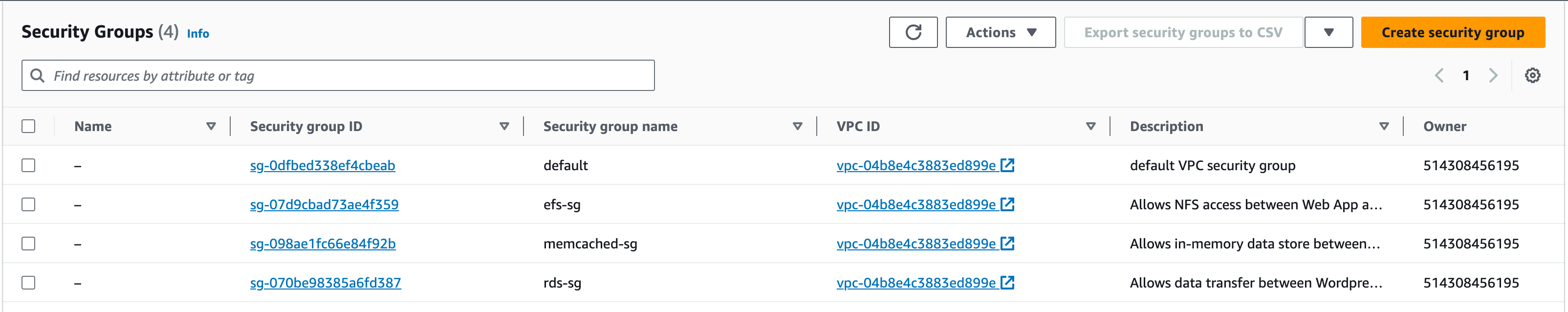
Before we deploy the Data resources, we need to have the Security Groups ready to attach to the resources. This will provide a layer of security to our data resources to control where the data is being received from and sent to, i.e., the web-app instances.
- In the services search bar, enter ‘EC2’ and open the EC2 service
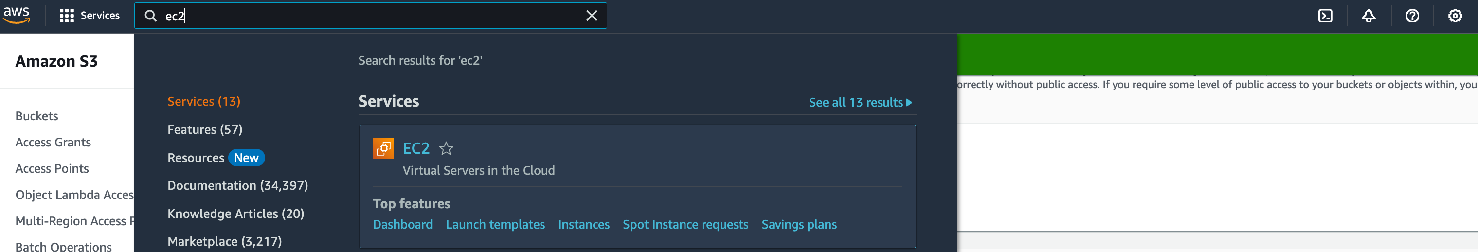
2. On the side panel, under ‘Network & Security’, choose ‘Security Groups’. Click on ‘Create Security Group’ and configure the SG :
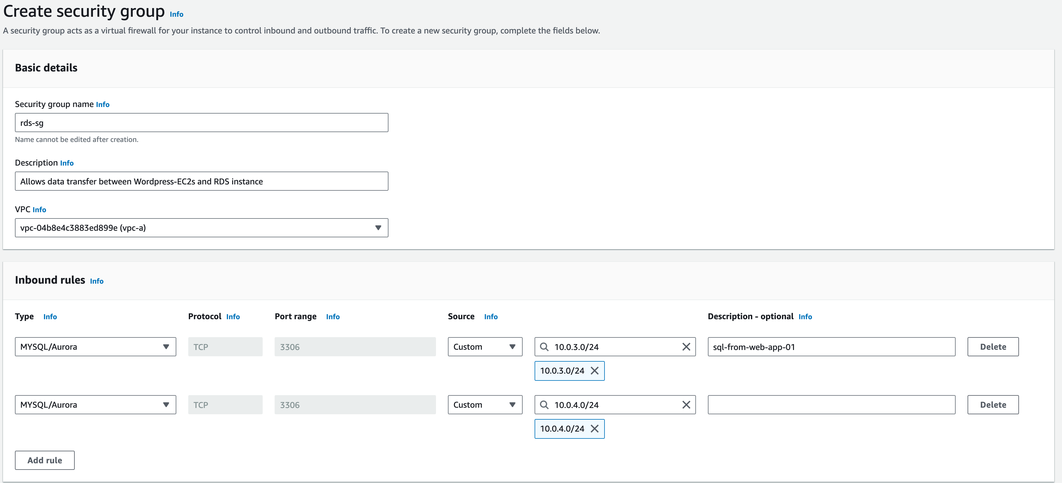
3. For the ‘Security Group Name’ enter ‘rds-sg’
4. ‘Description’: ‘Allows data transfer between WordPress-EC2s and RDS instance’
5. ‘VPC’: ‘vpc-a’
6. For the ‘Inbound Rules’, click on ‘Add rule’
7. Type: choose ‘MySQL/Aurora’ (you may need to scroll down)
8. Protocol: TCP, Port Range –3306 (should be automatically configured and greyed-out)
9. Source keep this as ‘Custom’ and enter ‘10.0.3.0/24’ (for the APP AZ-a subnet)
10. For the ‘Description’, enter ‘sql-from-web-app-01’
11. Repeat this process for another rule allowing ’10.0.4.0/24’ (for the APP AZ-b subnet)
12. Keep outbound rules as default (All traffic, Destination 0.0.0.0/0)
Setting up Memcached Security Groups
Now let’s create the Security Group for Memcached:
- In the services search bar, enter ‘EC2’ and open the EC2 service
2. On the side panel choose ‘Security Groups’ under ‘Network & Security’
3. Click on ‘Create Security Group’ and let’s configure for the Memcached SG:
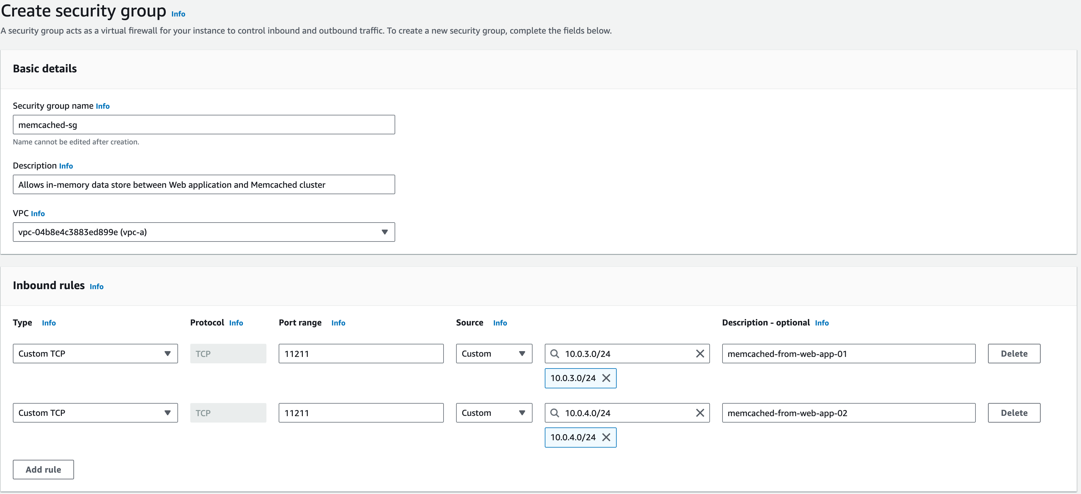
1. Security Group Name: ‘memcached-sg’
2. Description: enter ‘Allows in-memory data store between Web application and Memcached cluster’
3. VPC: vpc-a
4. ‘Inbound Rules’, click ‘Add rule’
- For the ‘Type’ choose ‘Custom TCP’
- For the ‘Port range’ choose ‘11211’
- For the ‘Source’, keep this as ‘Custom’ and enter ‘10.0.3.0/24’ (for the APP AZ-a subnet)
- For the ‘Description’, enter ‘memcached-from-web-app-01’
- Repeat this process for another rule allowing ’10.0.4.0/24’ (for the APP AZ-b subnet)
- Keep outbound rules as default (All traffic, Destination 0.0.0.0/0)

Security Group for EFS
Now, let’s create the Security Group for EFS:
- In the services search bar, enter ‘EC2’ and open the EC2 service
2. On the side panel choose ‘Security Groups’ under ‘Network & Security’
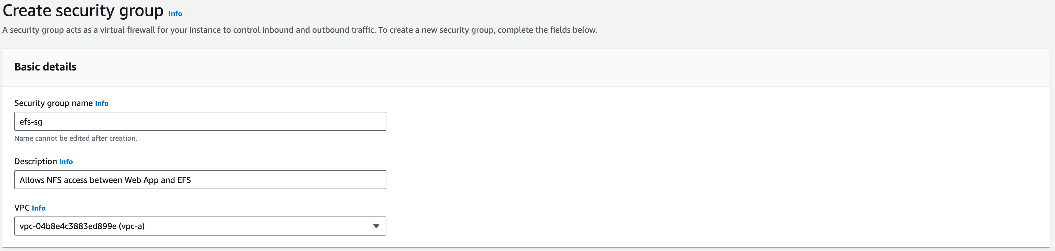
3. Click on ‘Create Security Group’ and let’s configure for the EFS SG:
1. For the ‘Security Group Name’ enter ‘efs-sg’
2. For the ‘Description’, enter ‘Allows NFS access between Web App and EFS’
3. Vpc: vpc-a
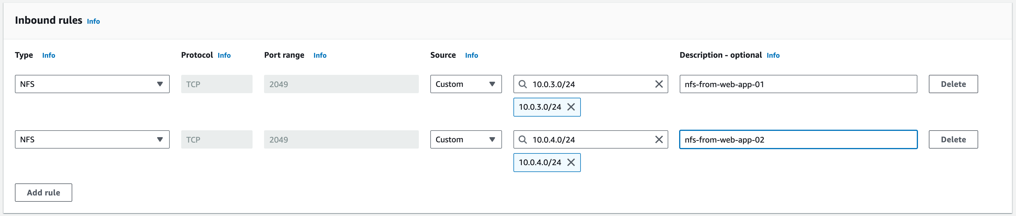
4. ‘Inbound Rules’, click on ‘Add rule’
- For the ‘Type’ choose ‘NFS’
- For the ‘Source’, keep this as ‘Custom’ and enter ‘10.0.3.0/24’ (for the APP AZ-a subnet)
- For the ‘Description’, enter ‘nfs–from-web-app-01’
- Repeat this process for another rule allowing ’10.0.4.0/24’ (for the APP AZ-b subnet) (nfs-from-web-app-02 in the description). This should look like the screenshot below:
Create the Amazon Relational Database Service (RDS) Instance
Let’s create the Amazon RDS instance and associated resources.
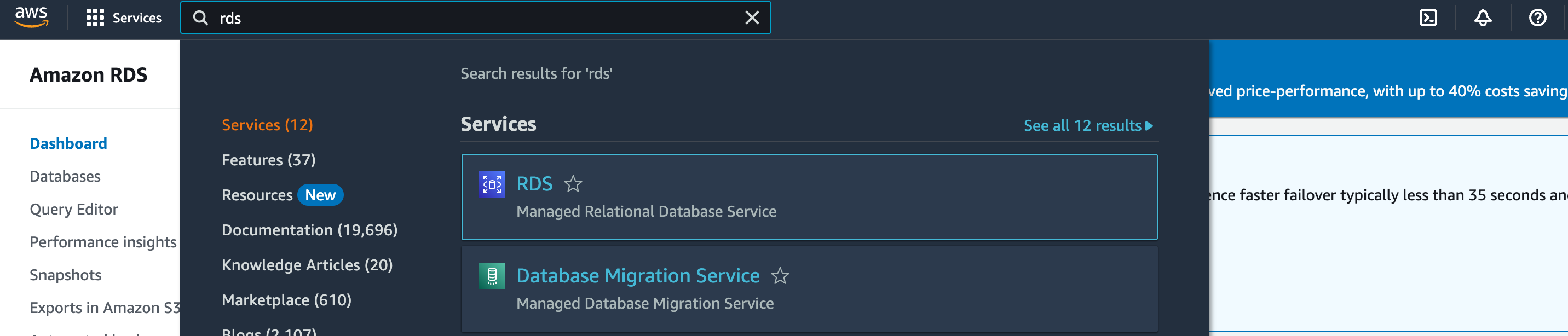
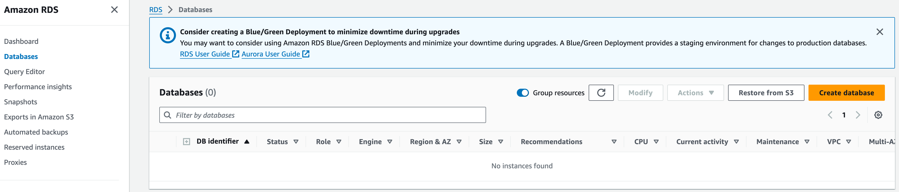
1. In the services search bar, enter ‘RDS’ and open the RDS service
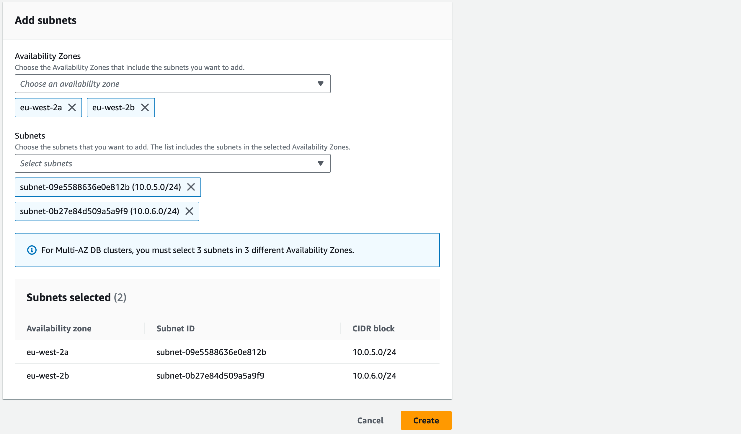
First, we need to create the Subnet Group:
Select ‘Subnet groups’ from the left-hand pane and click ‘Create DB subnet group’
Name: ‘rds-subnet-group’
Description: ‘Subnet group for RDS’
VPC: ‘vpc-a’
Add Subnets: Availability Zones – tick ‘eu-west-2a’ and ‘eu-west-2b’
Subnets: in the ‘eu-west-2a’ section tick the subnet with CIDR block 10.0.5.0/24’ and for the ‘eu-west-2b’ section tick ‘10.0.6.0/24’. This will create a subnet group containing both our data subnets.
Click ‘Create’. You should be able to view your created subnet group in RDS –> Subnet groups.
Now we have made our subnet group, Select ‘Database’ from the left-hand pane and click ‘Create Database’
Choose a database creation method: Select ‘Standard Create’
Engine options: ‘MySQL’.
Edition: ensure ‘MySQL Community’ is selected (should be by default as it is the only option).
Engine Version: 8.0.35.
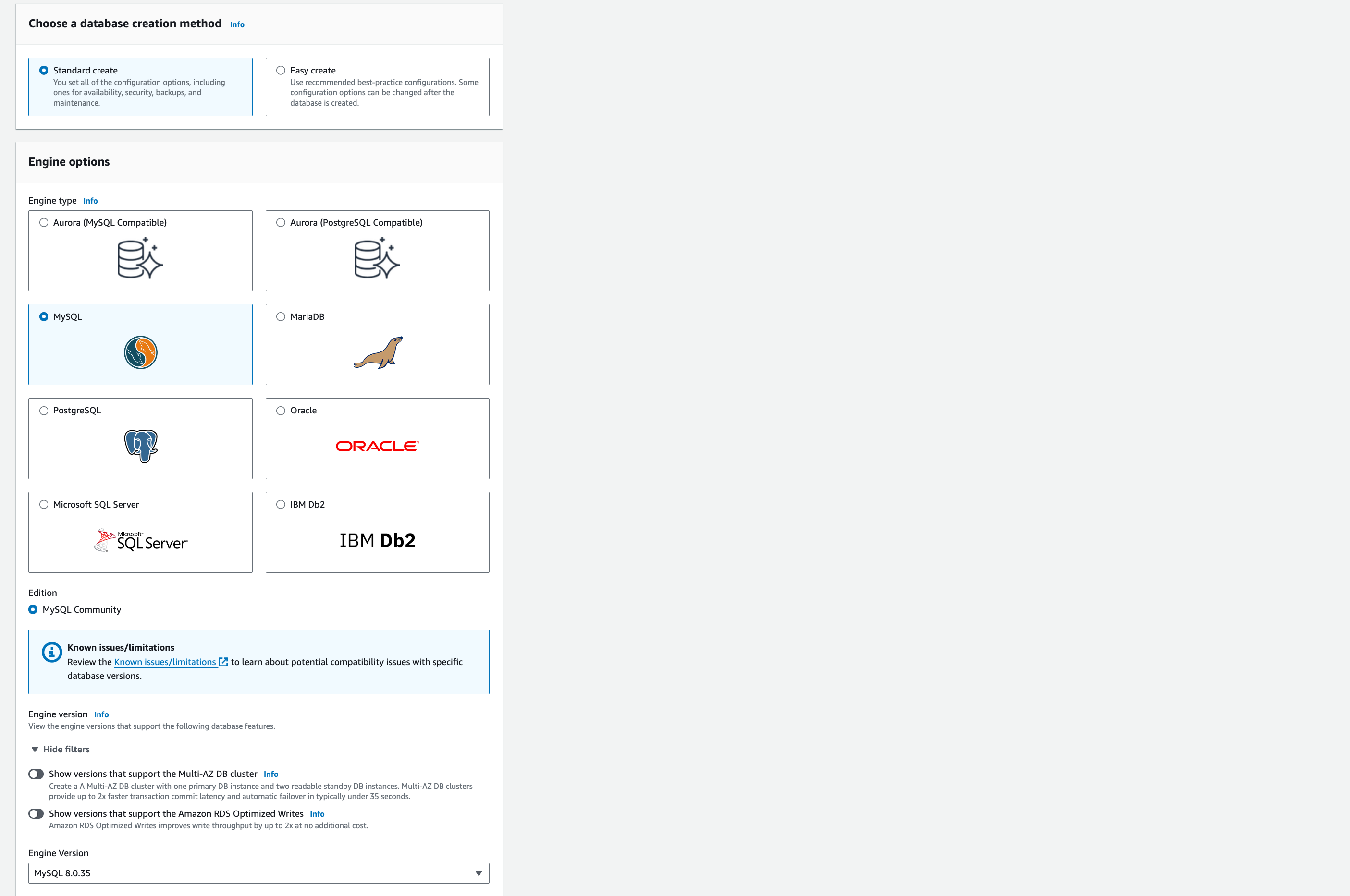
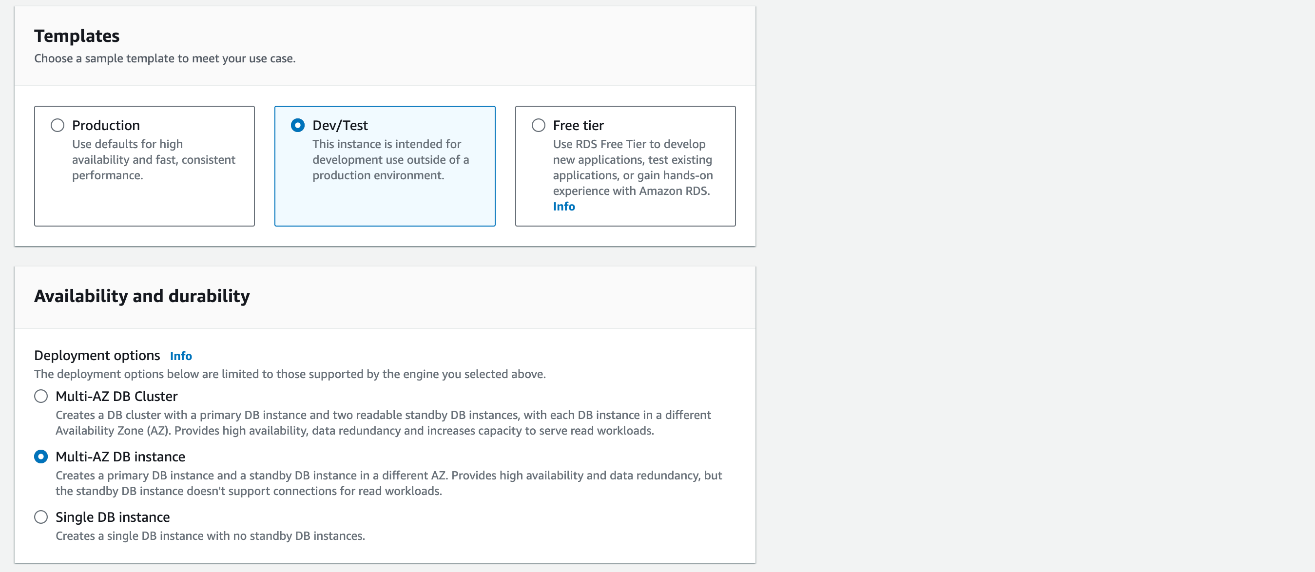
Templates: choose ’Dev/Test’. (The ’free tier’ option would be the cheapest to run but we want to create an environment with High Availability (HA). The best way to make our solution cost-effective and highly available is the ‘Multi-AZ DB instance’ requirements – compare the different ‘Deployment options’ notes in the screenshot).
Availability and durability: Multi-AZ DB Instance
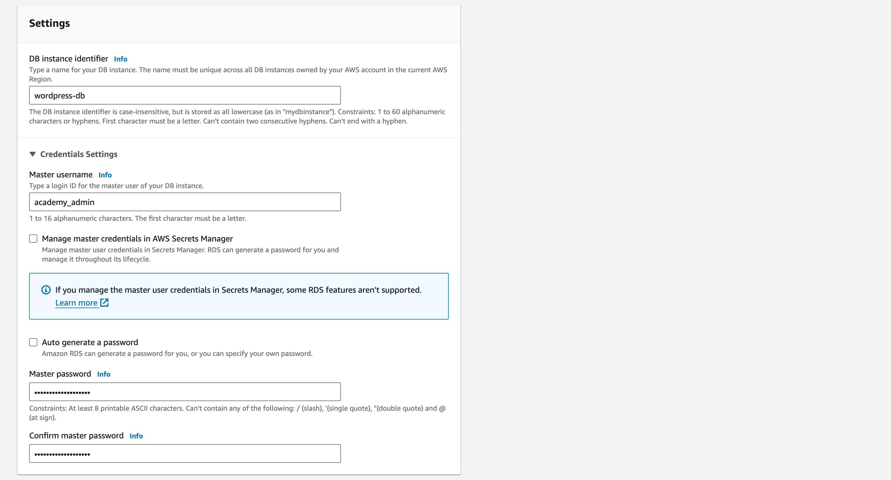
1.1. Give your DB an identifier name. For the demonstration, call it: ‘wordpress-db’
1.2. Master username: academy_admin
1.3. Master password: Your_Pasword123 (Note – passwords are case-sensitive).
1.4. Confirm master password – (ensure it is typed correctly)
1.5. Instance configuration: ‘Burstable classes’ for the instance type list and ‘db.t3.micro’ for the instance size
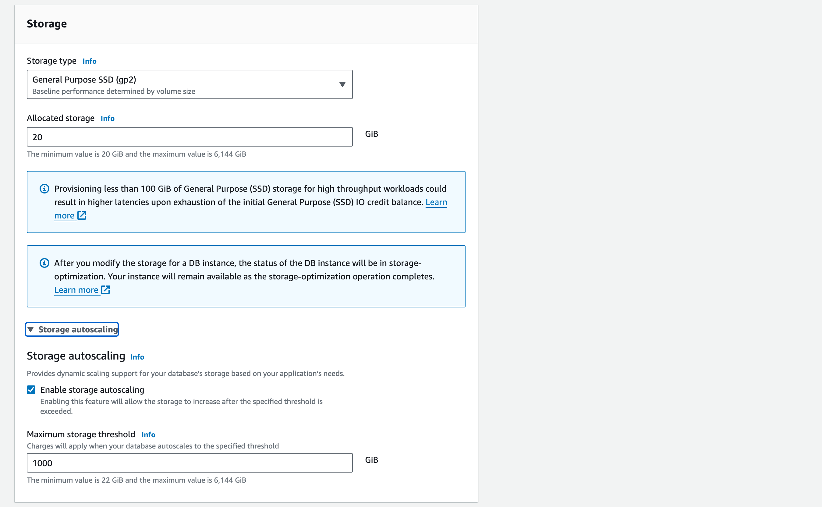
1.6. Storage: Storage type – General purpose SSD (gp2)
1.7. Allocated storage – 20GiB (this is the minimum value possible, for cost-effectiveness. Note the message below about potential high latencies. We can ignore this as there will only be minimal load on our database).
1.8. Storage autoscaling – tick ‘Enable storage autoscaling’
1.9. Maximum storage threshold – enter 1000 GiB
1.10. Connectivity: ‘Don’t connect to an EC2 compute resource’ (we will set this up manually later when we have created our EC2 instances)
1.11. Virtual Private Cloud (VPC): vpc-a (NB – take care here – see the message ‘After a database is created, you can’t change its VPC.’ If you select the wrong VPC then you will have to recreate the database from scratch)
1.12. For the ‘Security Group’, click the ‘X’ to delete the ‘default’ sg and select ‘rds-sg’ from the dropdown menu
1.13. Database authentication: select ‘Password authentication’
Monitoring: Tick ‘Enable Enhanced monitoring’ and keep the default settings.
1.14. For ‘Additional Configuration’:
1.14.1. Give your initial DB a name. For the demonstration, call it: ‘wordpress_db’
1.14.2. The ‘Parameter group’ contains specifications on how you want your master database and database cluster to be configured. For this demonstration, keep the ‘default’ DB and DB cluster parameter group
Backup: Tick ‘Enable automated backups’
1.14.3. Set the ‘backup retention period’ to 1 day (and tick ‘Copy tags to snaphots). This is the number of days our automated backups are retained before deletion
Backup window – no preference
Tick copy tags to snapshots
Backup replication – leave Enable replication in another AWS Region
Encryption: Tick Enable encryption
1.14.4. For the AWS KMS key, choose the (default aws/rds) KMS key
Keep all other settings as default, but untick ‘Enable deletion protection’
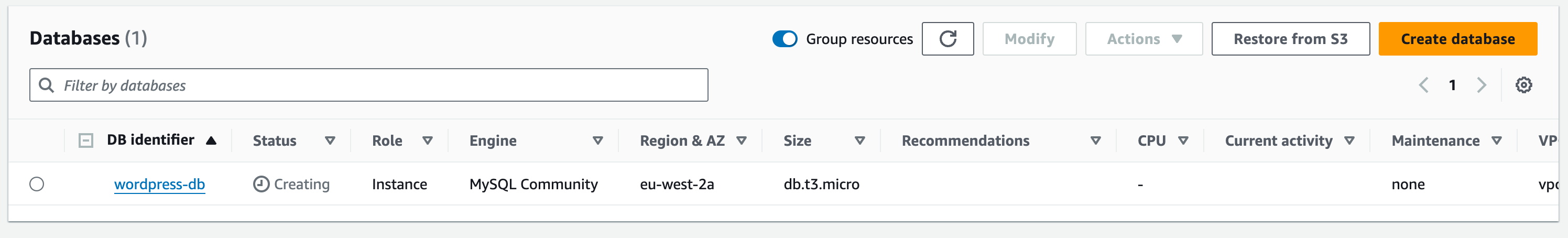
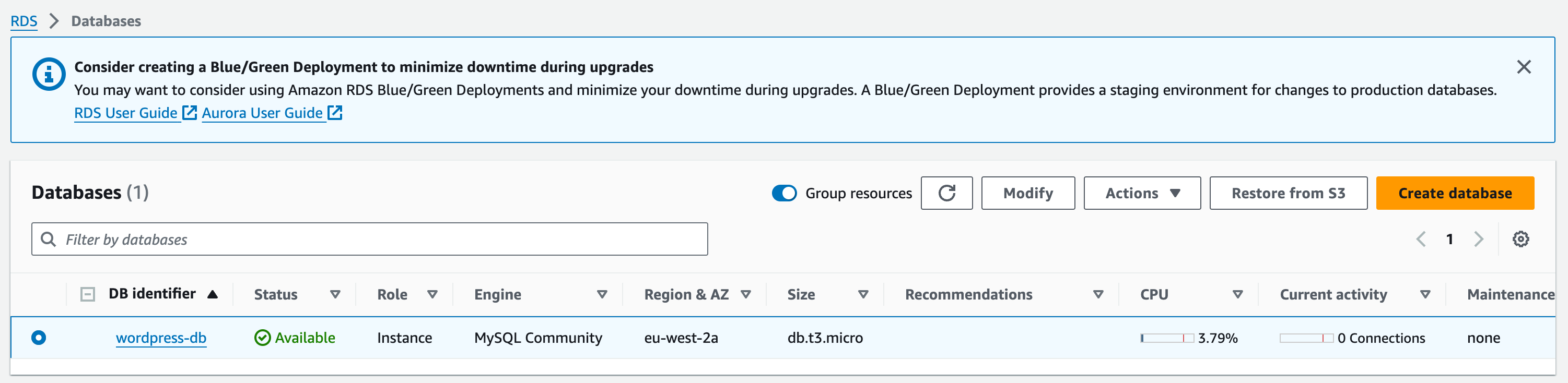
1.15. Then choose ‘Create Database’
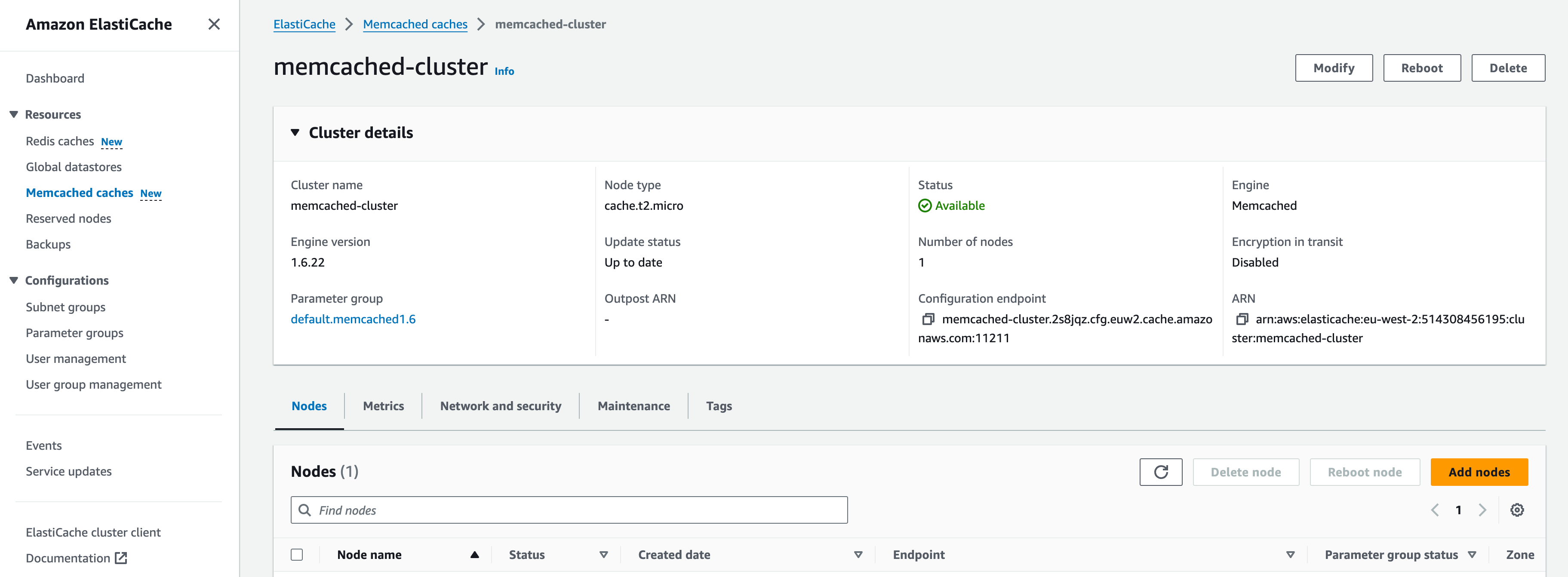
1.16. It might take a few minutes to reach ‘Available’ status but once created, your DB should look like:
Amazon Elasticache for Memcached
Let’s move onto building our Memcached cluster
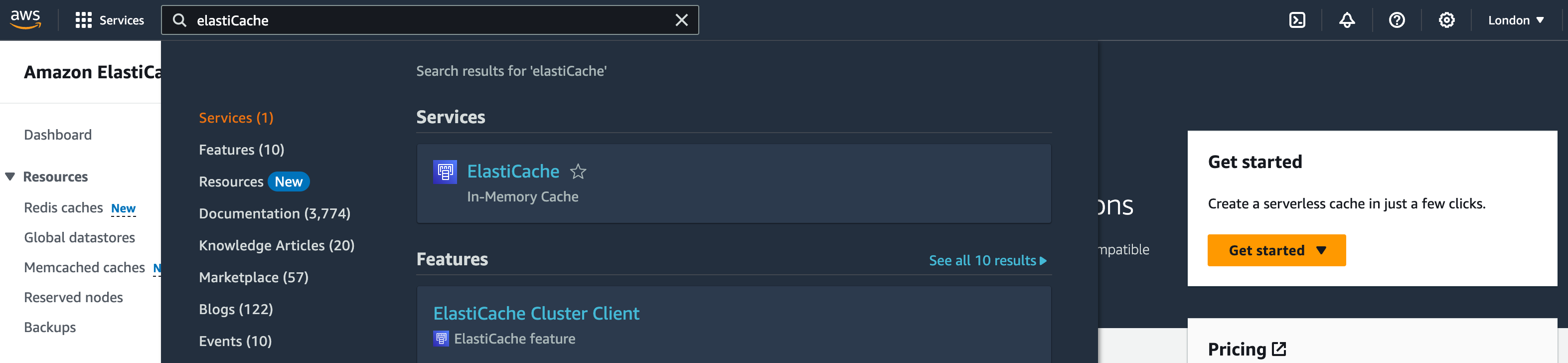
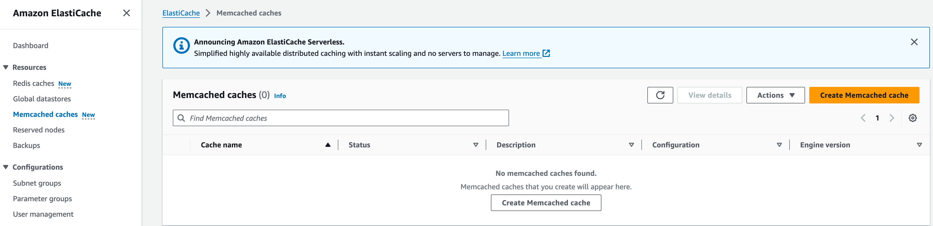
1. In the services search bar, enter ‘Elasticache’ and open the Elasticache service
Memcached Cluster Config.
1. Under ‘Resources’ on the side tab, go to ‘Memcached Caches’
2. Choose ‘Create Memcached cache’
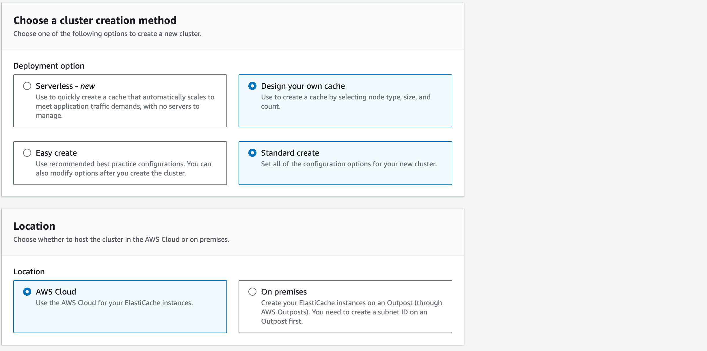
3. For Create choose “Design your own Cache” and then “Standard Create” instead of “Easy Create”. Standard Create will allow us to edit the cluster settings.
3. For Location select ‘AWS Cloud’
4. Here we’ll detail the configuration for our Memcached Cluster
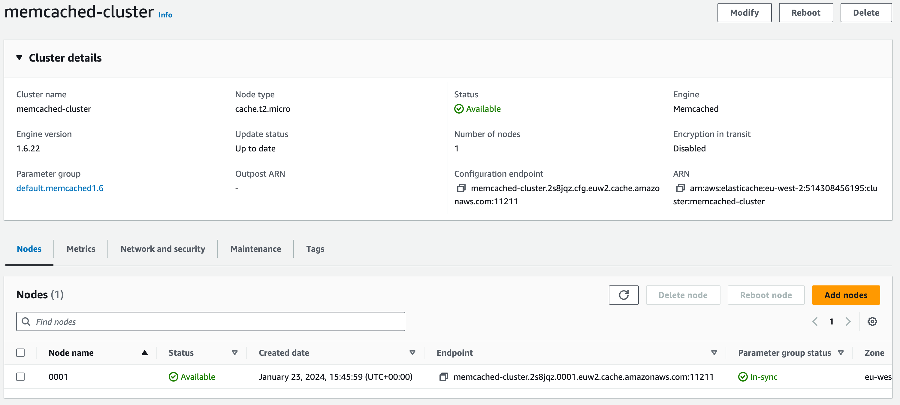
4.1. For the ‘Cluster Info’ give the ‘Name’, ‘memcached-cluster’. You can give it a ‘Description’ which is always good practice but not necessary for the purpose of this workshop
4.2. For the ‘Cluster Settings’ choose the most recent ‘Engine version’ (1.6.17 at the time of writing).
4.3. Keep the ‘Port’ as ‘11211’
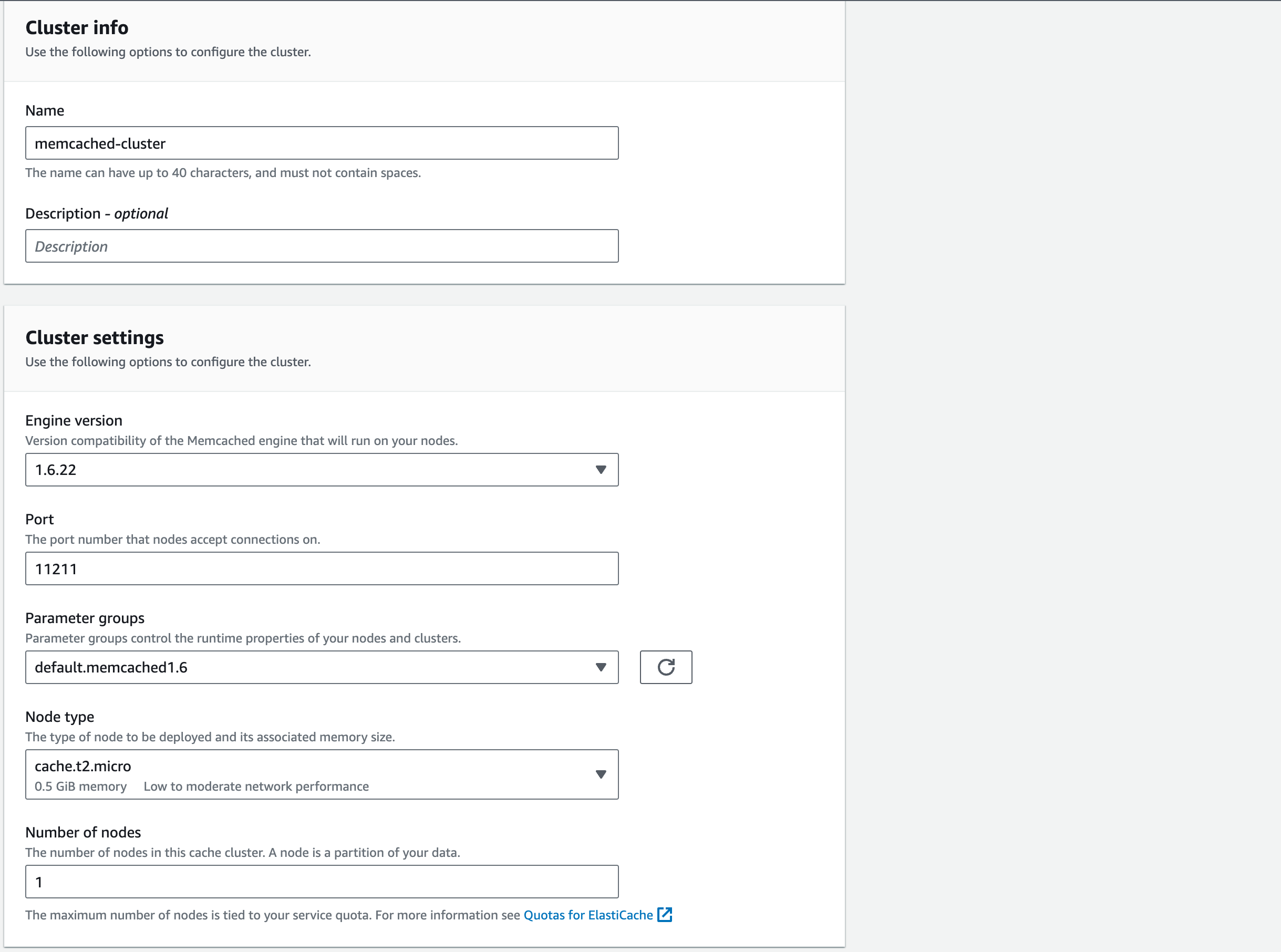
4.4. Similar to RDS, the ‘Parameter groups’ contains specifications on how we want our Memcached cluster to be configured. For this demonstration, we’ll keep this as the ‘default.memcached1.6’
4.5. For the ‘Node type’, choose ‘cache.t2.micro’. Each node is a fixed-size chunk of secure, network-attached RAM. Each node runs an instance of Memcached
4.6. For the ‘Number of nodes’ choose 1. This will be increased later in the Academy for high availability.
Memcached Subnet Group
1. The Subnet Group is the collection of subnets that we want to deploy our Memcached Cluster into. Choose ‘Create a new subnet group’
1.1. Give the ‘Name’ of the subnet group ‘memcached-subnet-group’. You can give it a ‘Description’ which is always good practice but not necessary for the purpose of this demonstration
1.2. Choose ‘vpc-a’ (if the VPC name is not displayed, check the VPC ID for vpc-a in the VPC section on the management console)
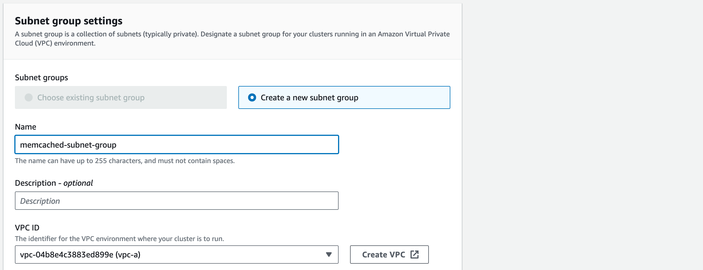
1.3. For the ‘Selected subnets’ we do not want to connect the subnets that we are using to host the Web APP.
We do want to include the DATA subnets – the subnet name may not be there. Refer to the architecture diagram to try to work out the CIDR blocks for the DATA subnets:
To amend this, click on ‘Manage’ and check that the correct Data subnets are ticked.
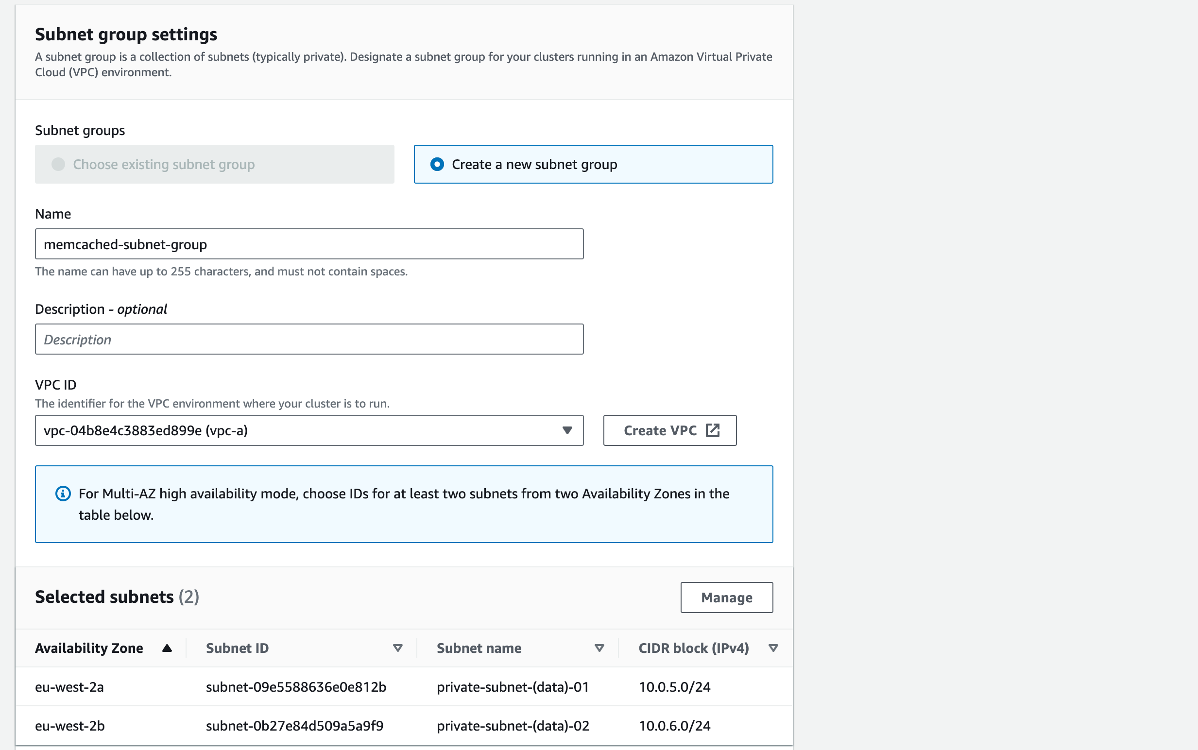
(10.0.5.0/24 and 10.0.6.0/24).
1. For Availability Zone placements’ we’ll eventually want multiple nodes spread across 2 AZ’s. For now we’ll just use one. Choose ‘Specify Availability Zones’ and you’ll see the Node 0001 has been assigned to eu-west-2a
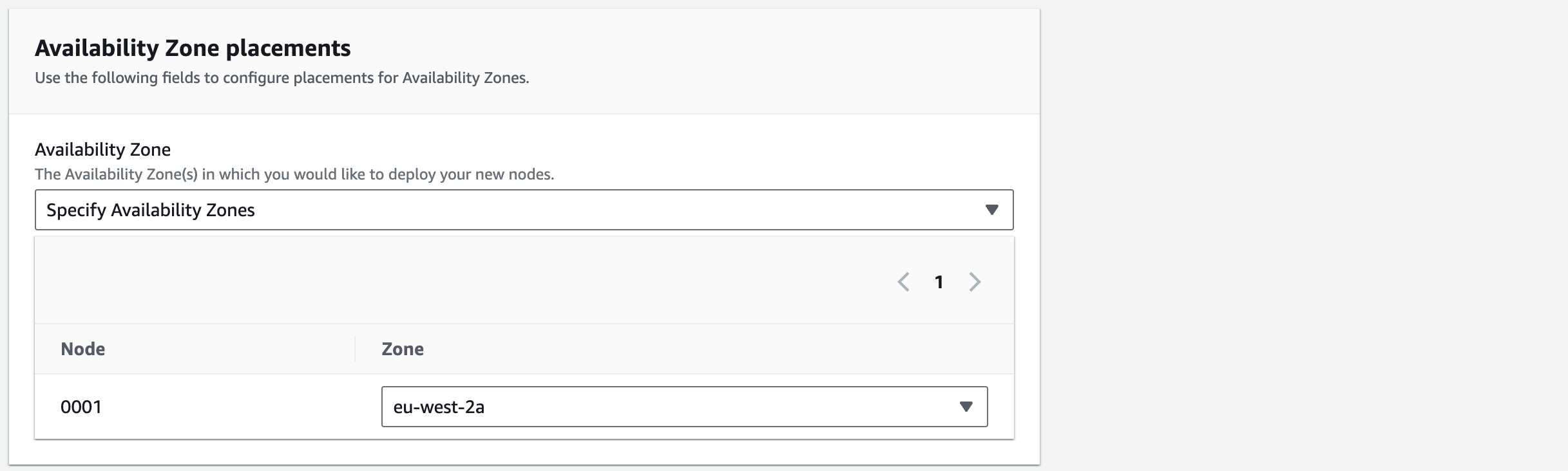
1.1. Click ‘Next’
2. For the ‘Selected Security Groups’ click ‘Manage’ and select the ‘memcached-sg’ security group
3. Select ‘No preference’ for the ‘Maintenance Window’ as we don’t mind when updates occur (such as patching an operating system)
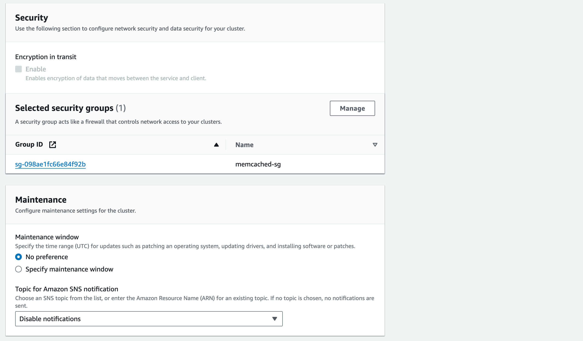
4. We will ‘Disable notifications’ for now but once we’ve configured SNS topics in Section 8, we can come back to add SNS notification
Review the configuration and when you’re happy click ‘Create’. Once created, it should look like this:
Amazon EFS
Before creating this resource, we need to retrieve the AWS Managed key from KMS
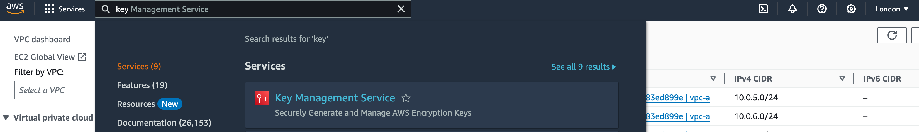
1. In the services search bar, enter ‘KMS’ and open the Key Management Service service
2. Click on ‘AWS managed keys’ on the side bar
3. Look for the ‘aws/elasticfilesystem’ alias and copy & paste the corresponding ‘Key ID’ to a .txt file. We’ll need this when deploying the EFS
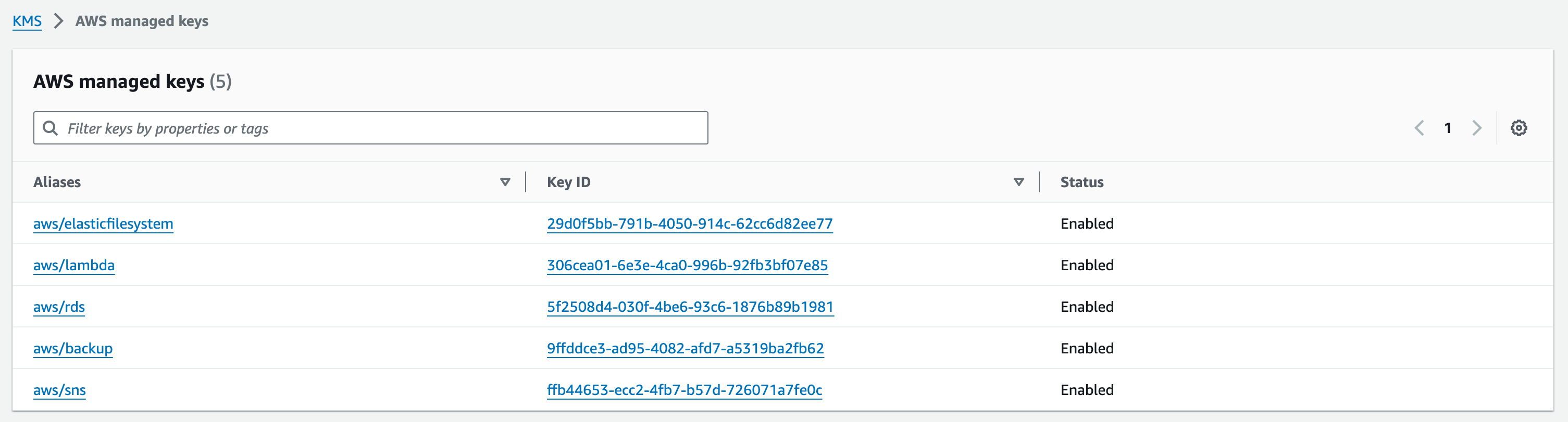
NOTE
The managed key we are looking for,
aws/elasticfilesystem, does not exist if an EFS was not previously created. The key will be auto-created later in EFS Configuration in the next section.
EFS Configuration
Now, let’s start building our final resource for this section: Amazon Elastic File System (EFS)
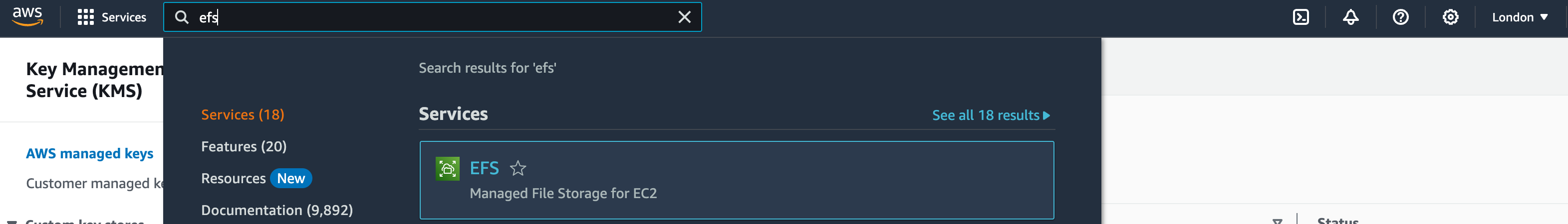
1. In the services search bar, enter EFS and open the EFS service
2. Choose the ‘File Systems’ option on the side tab, and click ‘Create file system’
3. Choose ‘vpc-a’. We want to go into finer detail with our configuration before entering any more details, choose ‘Customize’
3.1. Give your file system the name: ‘efs’
3.2. For ‘Virtual Private Cloud (VPC)’ choose ‘vpc-a’
3.3. Choose the ‘Standard’ option for Storage Class option as we want our file system to store data redundantly across multiple AZs
3.4. Keep ‘Enable automatic backups’ ticked
3.5. For the lifecycle management, we want to move data that hasn’t been accessed within the last 30 days, from our standard EFS to Infrequently accessed. Then we want the data to move out of IA to our standard EFS on first access
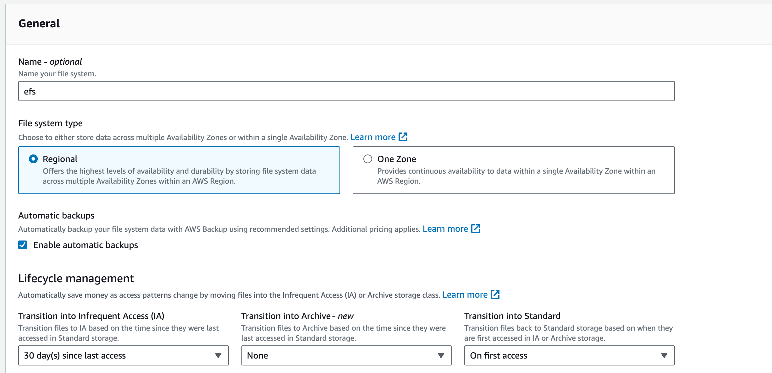
Encryption: Tick Enable encryption of data at rest
Performance settings:
3.7. The throughput is a measure of how much data our EFS system can process in a given amount of time. Choose ‘Bursting’ for this option which will scale relative to the size of the EFS system.
Additional settings:
3.6. Choose ‘General Purpose’ for the performance mode
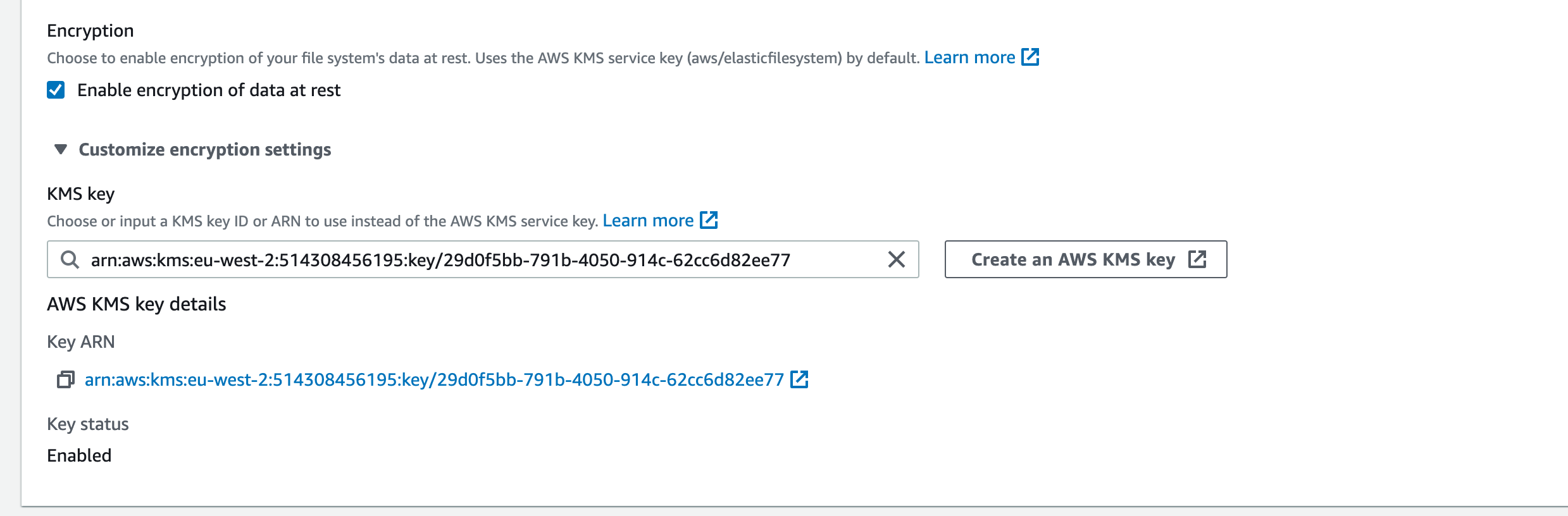
3.9. Click on the ‘Customize encryption settings’ dropdown. This is where we need to define the KMS key we’d like to use for encrypting/decrypting our data. Enter the ‘Key ID’ that you saved in a .txt file at the beginning of this section and press ‘Enter’. It should then look like this:
NOTE
As mentioned in the previous section, The managed key we are looking for,
aws/elasticfilesystem, does not exist if an EFS was not previously created. If you do not have the ID for they key requested here, you can leave the KMS Key field blank and it will default to the EFS Service Key.
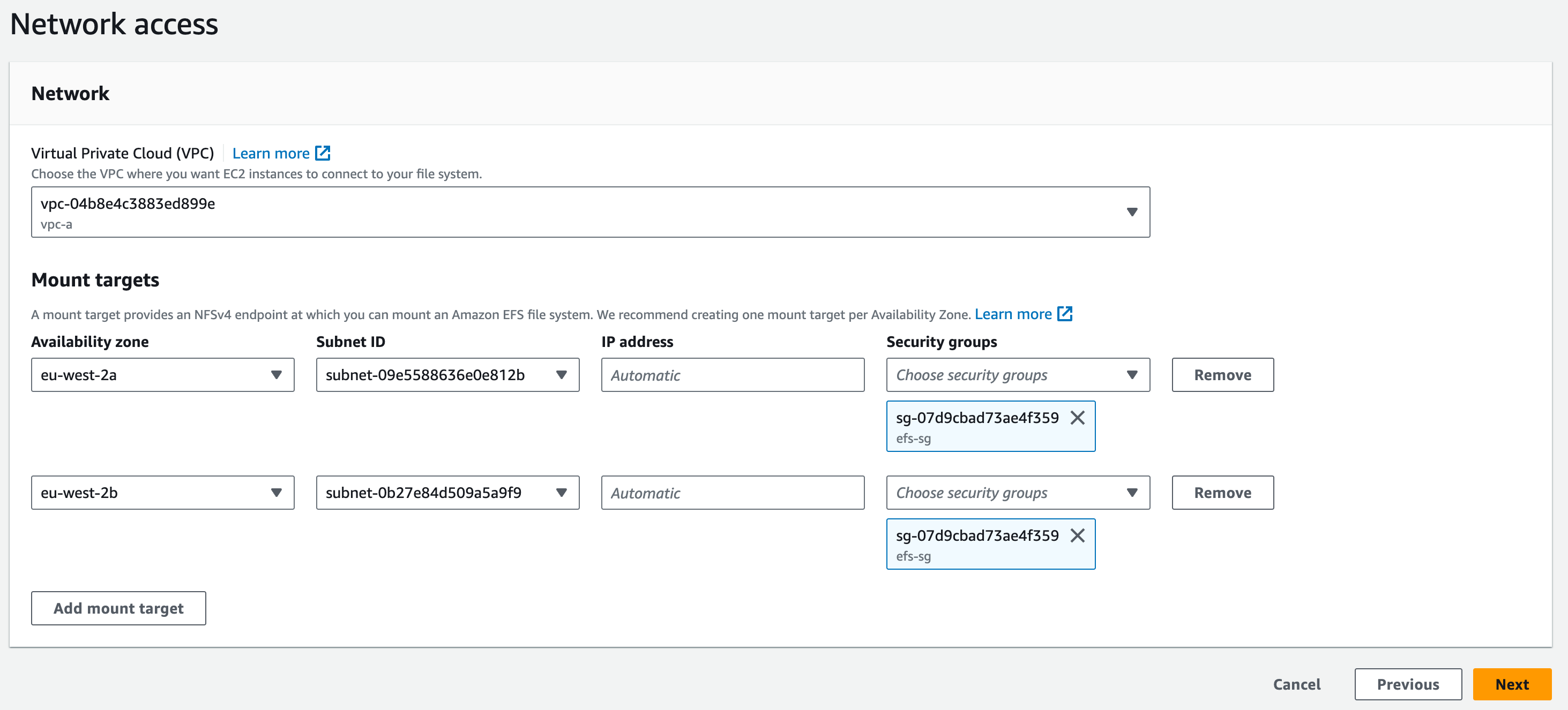
3.11. Mount Targets: select subnet-(data)-01 and subnet-(data)-02. This will mount our EFS system to the Data layer of our stack. We then select ‘efs-sg’ for the ‘Security groups’ and delete the ‘default’ security groups. Click ‘Next’
3.12. No File System policies are necessary for this demonstration
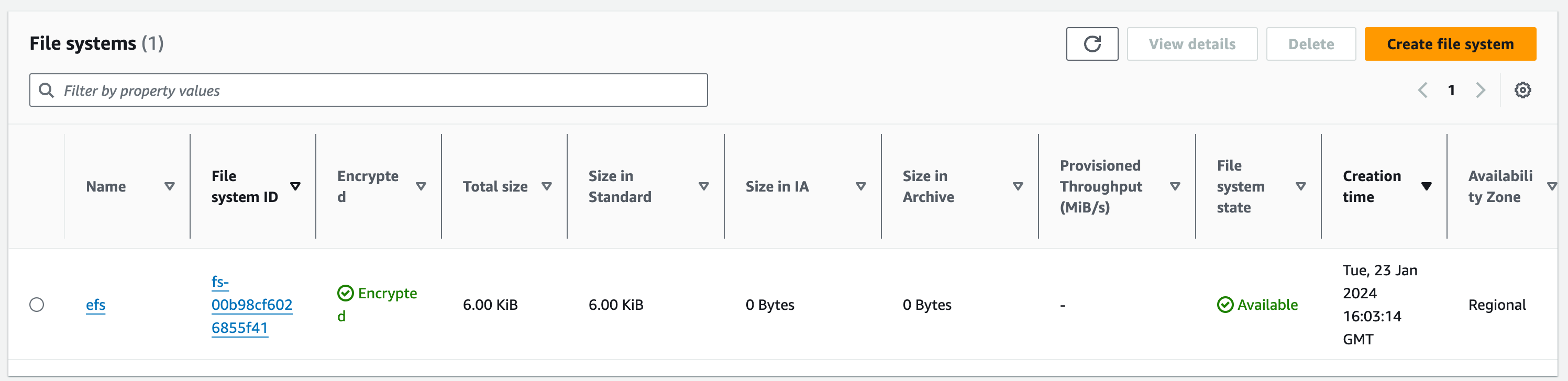
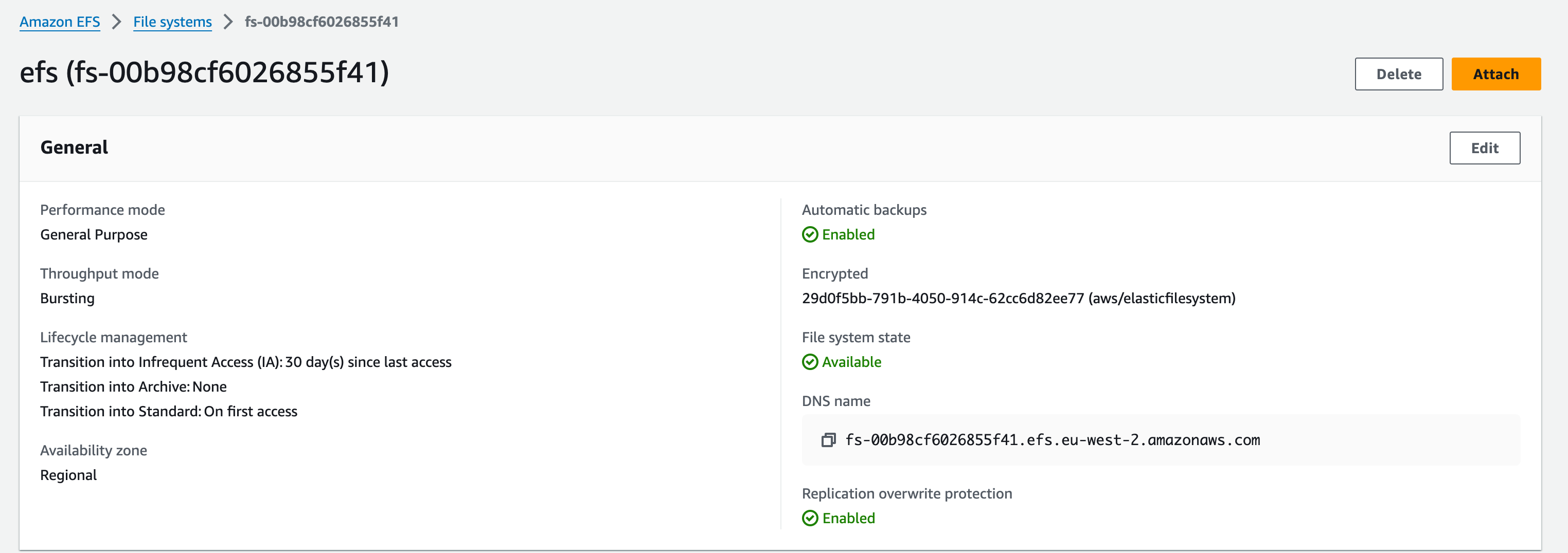
Review the configuration and when you’re happy click ‘Create’. Once deployed, it should look like this:
Security Groups
Start by creating the security groups for both the EC2 instance and the Application Load Balancer. navigate to the EC2 service in the AWS console and click on ‘security groups’ on the left pane.
In the right top corner click the orange button which says Create Security Group.
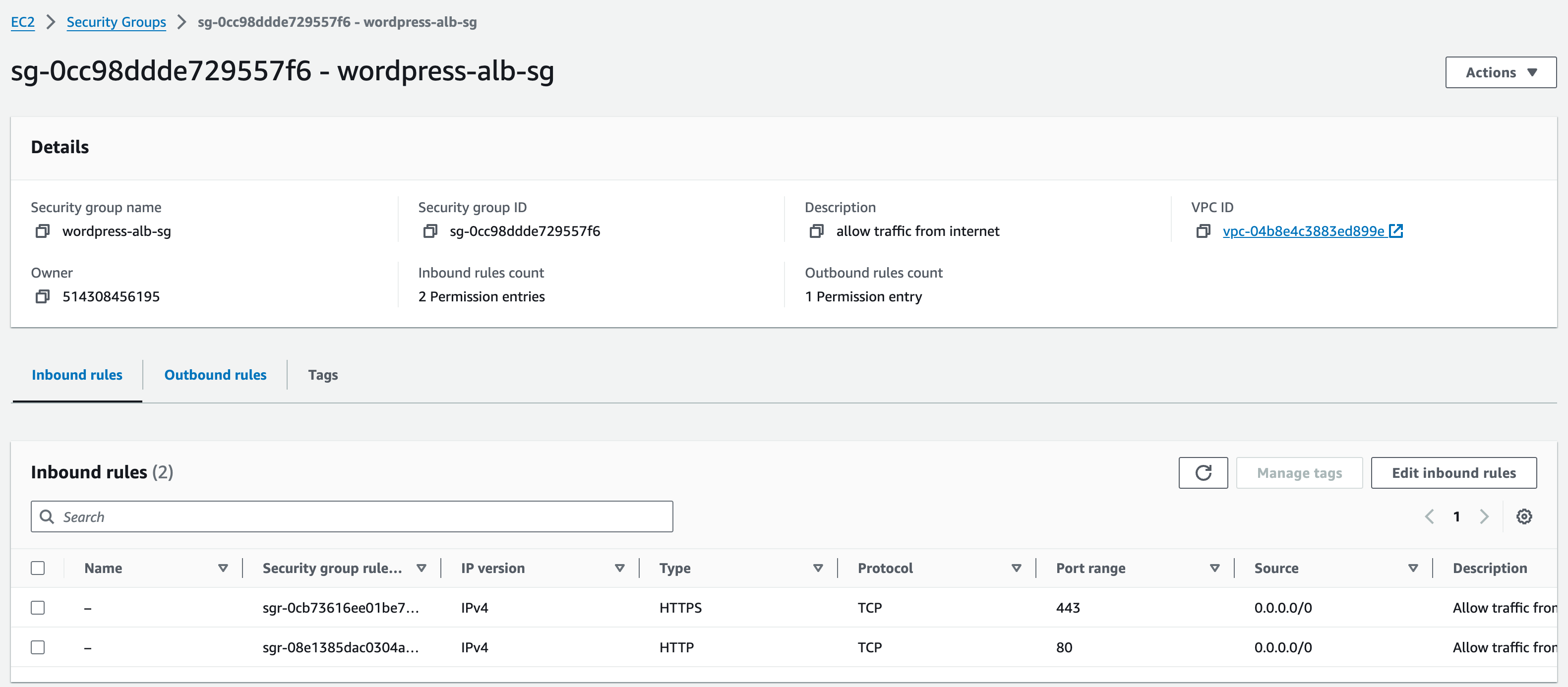
This security group is going to be for the Application Load Balancer (ALB)
Fill in the basic details section, we need to name the security group, describe, and select the VPC which will be vpc-a.
Name: wordpress-alb-sg
Description: allow traffic from internet
In the inbound rules section, click ‘add rule’, select type ‘HTTP’ from the drop-down menu. Click ‘add rule’, repeat the previous steps but this time select HTTPS.
Change the Source to ‘Anywhere-IPv4’ on both inbound rules (if not already there) then input the CIDR range of vpc-a (0.0.0.0/0). Leave outbound rules as they are. Click ‘done’.
Add default tags for owner and project.
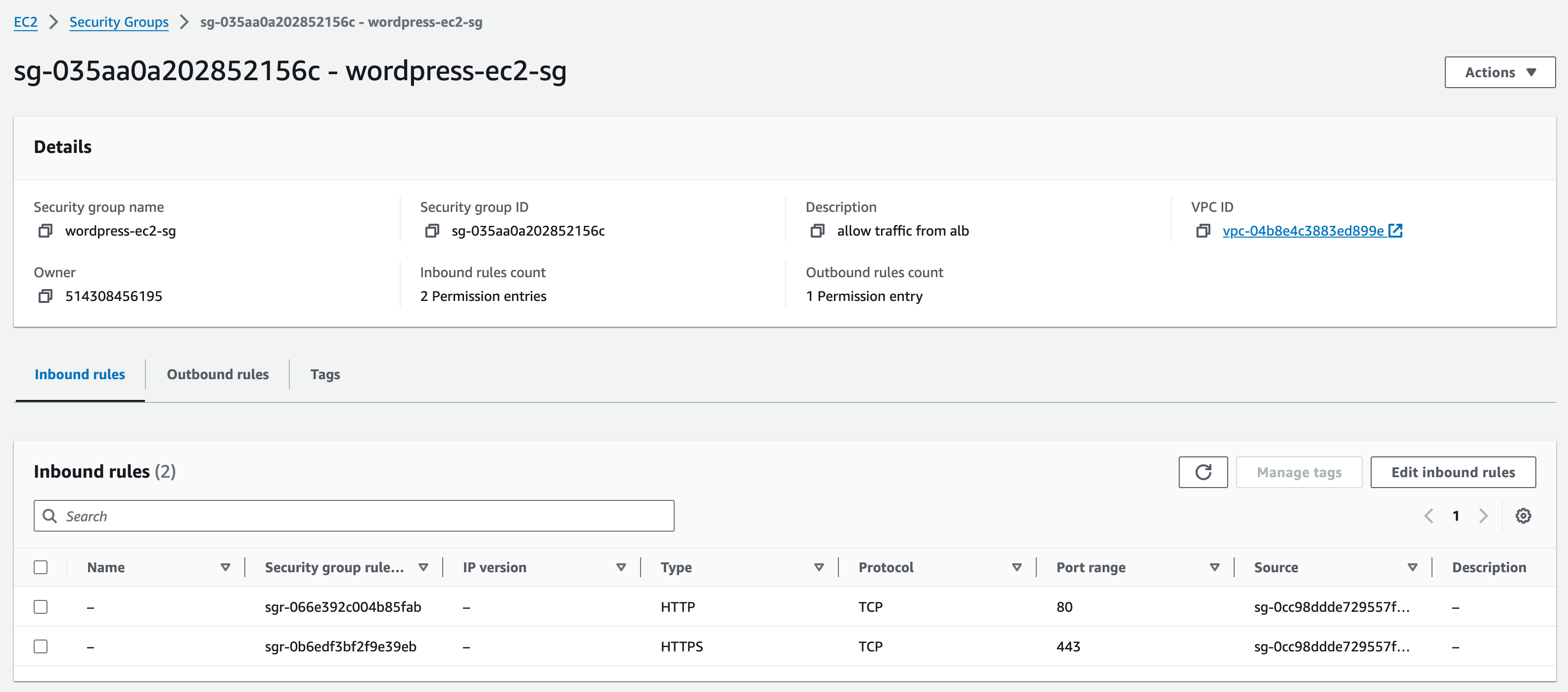
Now you need to create the security group for the EC2 instance. Go back to the security groups page where you can see the orange Create Security Group button and select it.
Similar to the previous Security Group you created, in the basic details section fill in:
Name: wordpress-ec2-sg
Description: allow traffic from alb
VPC: vpc-a
In the inbound rules section, follow the same few steps again, adding two rules (HTTP and HTTPS), changing the source to custom, but this time when choosing the custom source (on both rules) we are going to select the previous security group we created for the ALB (start typing ‘wordpress-alb-sg’ and select it)
Add default tags for owner and project.
Once again, leave outbound rules as they are and press the Create security group Button.
Note: Security groups are ‘stateful’, meaning you do not need to add rules for return. Therefore, any rule that allows traffic into an EC2 instance, will automatically allow responses to pass back out to the sender without an explicit rule in the Outbound rule set.
WordPress EC2 Instances
Now, we are going to create two EC2 instances – one in each of the private app subnets in vpc-a
Head over to the EC2 console page and click instances which is located in the left-hand side of the page. Now click on the orange button Launch Instances in the top right-hand corner.
Input the name as ‘wordpress-01’. Click the blue ‘add additional tags’ link. ‘Name’ should appear as wordpress-01’.
Application and OS Images: Choose an Amazon Machine Image (AMI) – Click ‘Amazon Linux’ then Select the option [Amazon Linux 2 AMI (HVM) – Kernel 5.10, SSD Volume Type] (this should already be selected by default).
Instance Type: t2.micro
Key Pair: select ‘Create new key pair’
Enter ‘Key pair name’ as ‘wordpress-key’. Keep ‘Key pair type’ as ‘RSA’ and ‘Private key file format’ as ‘.pem’
Click ‘create key pair’. The key pair will be downloaded into your ‘downloads’ folder.
Network settings: click ‘Edit’
VPC – vpc-a
Subnet: private-subnet-(app)-01
Auto-assign public IP: disable
Firewall (security groups): select ‘Select existing security group’
Security group name: select ‘wordpress-ec2-sg’
At the bottom of the page, leave ‘storage’ as it is.
Click the arrow next to ‘advanced details’ to expand this section.
In the Advanced Details section, we need to paste our userdata that will install WordPress and any necessary packages on start-up/creation.
You can find the user data here:
See the Notes under the user data as you will need to change the values on lines 6+7
- #!/bin/bash
- db_root_password=Mobilise_Academy123
- db_username=academy_admin
- db_user_password=wordpress–pass
- db_name=wordpress_db
- db_host=(REPLACE WITH YOUR DB ENDPOINT FROM RDS CONSOLE PAGE e.g.wordpress–db.cbeal3ktsu05.eu–west–2.rds.amazonaws.com)
- INITS=(REPLACE WITH YOUR INITIALS IN LOWER CASE)
- sudo yum update –y
- sudo yum install –y httpd
- sudo service httpd start
- sudo amazon–linux–extras install –y mariadb10.5 php8.2
- sudo yum clean metadata
- sudo yum install –y php php-{pear,cgi,common,curl,mbstring,gd,mysqlnd,gettext,bcmath,json,xml,fpm,intl,zip,imap,devel} git unzip
- # install imagick extension for wordpress
- yum –y install gcc ImageMagick ImageMagick–devel ImageMagick–perl
- pecl channel–update pecl.php.net
- printf “\n” | pecl install imagick
- chmod 755 /usr/lib64/php/modules/imagick.so
- cat <<EOF >>/etc/php.d/20–imagick.ini
- extension=imagick
- EOF
- wget https://github.com/mobilise-academy/wordpress/archive/refs/heads/main.zip -O /tmp/wordpress.zip
- cd /tmp
- unzip /tmp/wordpress.zip
- sudo usermod –a –G apache ec2–user
- sudo chown –R ec2–user:apache /var/www
- mv wordpress–main/* /var/www/html
- cp /www/html
- sed -i “s/INITS/$INITS/” /var/www/html/wp-config.php
- cd /var/www/html
- # Change permission of /var/www/html/
- chown -R ec2-user:apache /var/www/html
- # chmod -R 774 /var/www/html
- # enable .htaccess files in Apache config using sed command
- sed -i ‘/<Directory “\/var\/www\/html”>/,/<\/Directory>/ s/AllowOverride None/AllowOverride all/’ /etc/httpd/conf/httpd.conf
- #Make apache and mysql to autostart and restart apache
- systemctl enable httpd.service
- systemctl enable mariadb.service
- systemctl restart httpd.service
Copy and paste the data into this box and on line 6; edit the code to include the url of your RDS DB endpoint. You can find this in the RDS console
You also need to replace the value for INITS with your initials
So, for example, if your initials were TJ your user data would look like this:
- db_host=wordpress–db.cbeal3ktsu05.eu–west–2.rds.amazonaws.com
- INITS=tj
Finally, review the summary on the right-hand-side of the screen and click ‘launch instance’
Repeat the steps again for the second instance
You now need to create another EC2 instance following the same steps in section 2.1. Note the following:
Use a different name (wordpress-02)
Use the same key pair (wordpress-key) instead of making a new one
Select the other private app subnet – ‘private-subnet-(app)-02’ which is in a different availability zone
Use the same security group (wordpress-ec2-sg) instead of making a new one
Application Load Balancer (ALB)
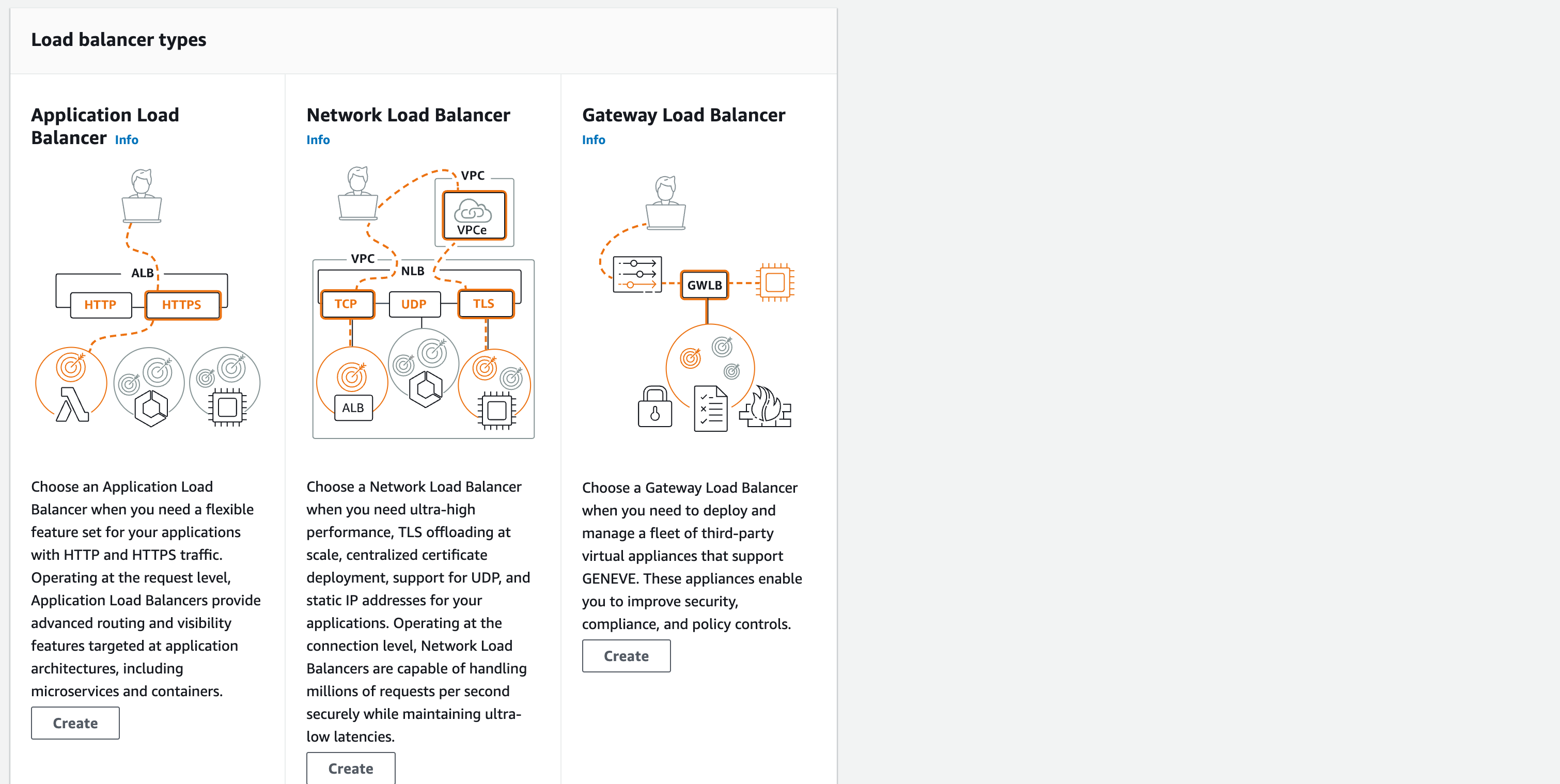
Now we need to create the ALB and associated target group. Navigate over to the Load Balancer service which is located in the left-hand pane of the EC2 console. And select the blue button Create Load Balancer. When it asks what type of Load Balancer you want to create select the ’create’ button under Application Load Balancer type.
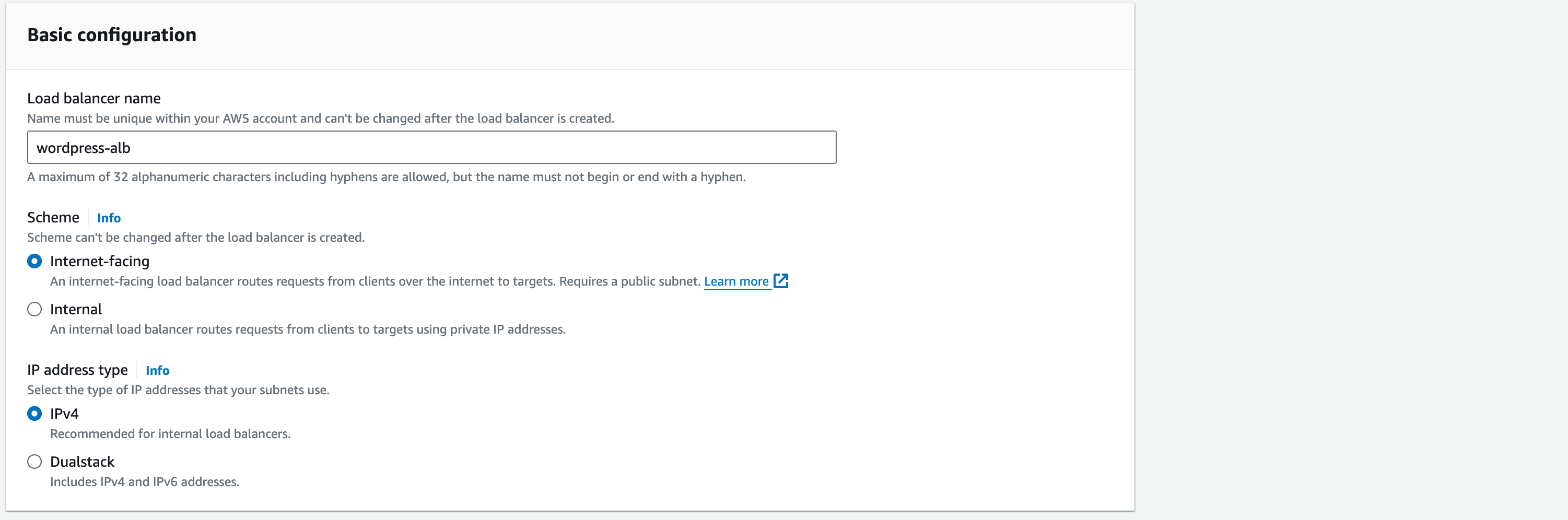
In the basic configuration section:
Load Balancer Name: wordpress-alb
Scheme: Internet-facing
In the Network mapping section:
‘VPC’ select ‘vpc-a’.
Mappings: select both Availability Zones that are there – this is where both our public subnets are.
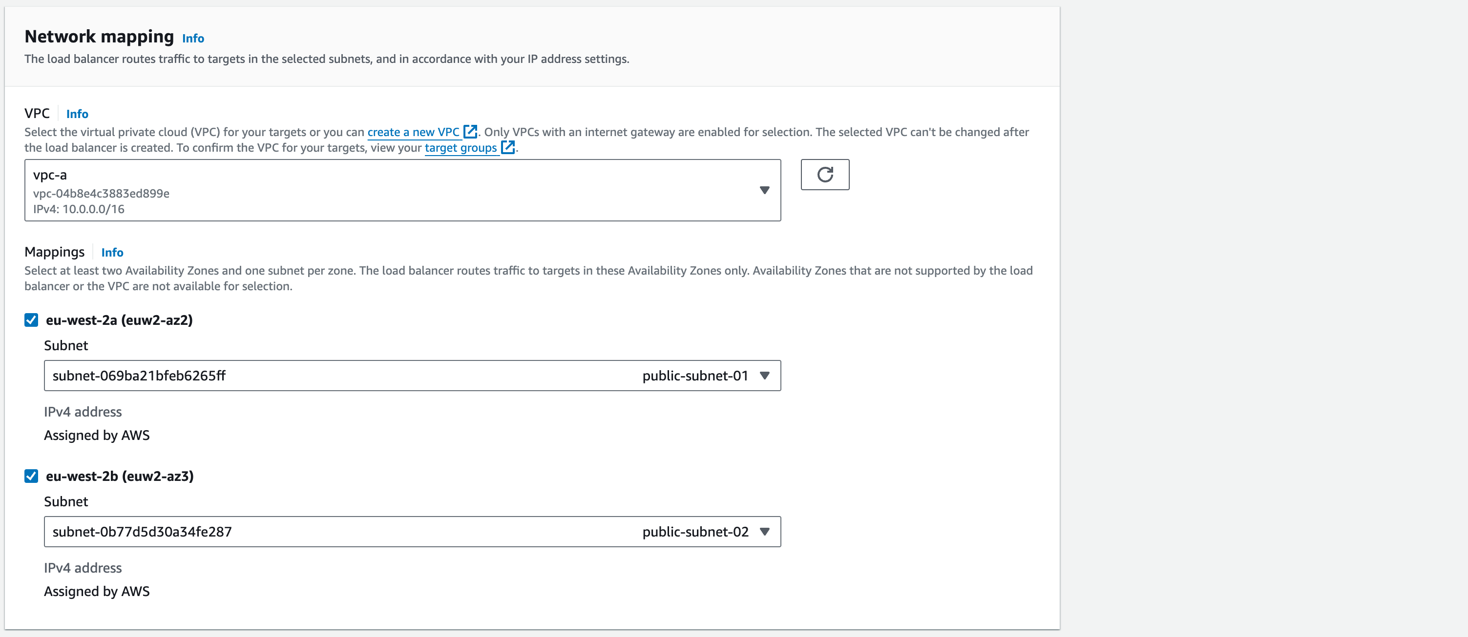
Confirm that in both drop down menus the public subnets you created are the ones selected.
In the security groups section, delete the default security group AWS have automatically assigned to this ELB by selecting the cross.
Then in the dropdown menu you need to select the security group that you created for the ALB. And ensure it shows up in place of the default one that you created earlier.
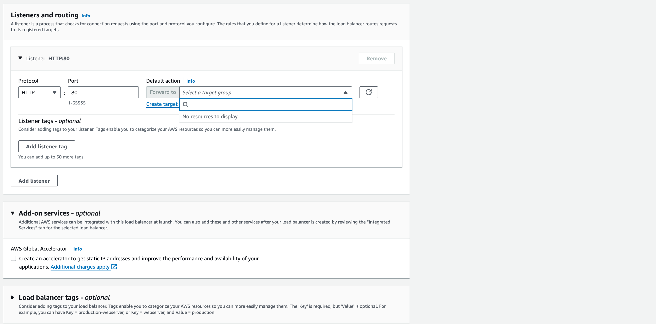
Listeners and routing:
Protocol: HTTP, Port: 80
Default action: click the ‘Create target group’ link – it will open in a new browser tab.
‘Basic configuration’: Instances,
Target group name: wordpress-target-group.
Protocol: HTTP, Port: 80
Double-check that the VPC selected is vpc-a.
Protocol version: HTTP1
‘Health Checks’: Keep ‘Health Check Protocol’ and ‘Health Check Path’ with default settings. Select the arrow next to Advanced health check settings.
Change the values to those shown in the screenshot.
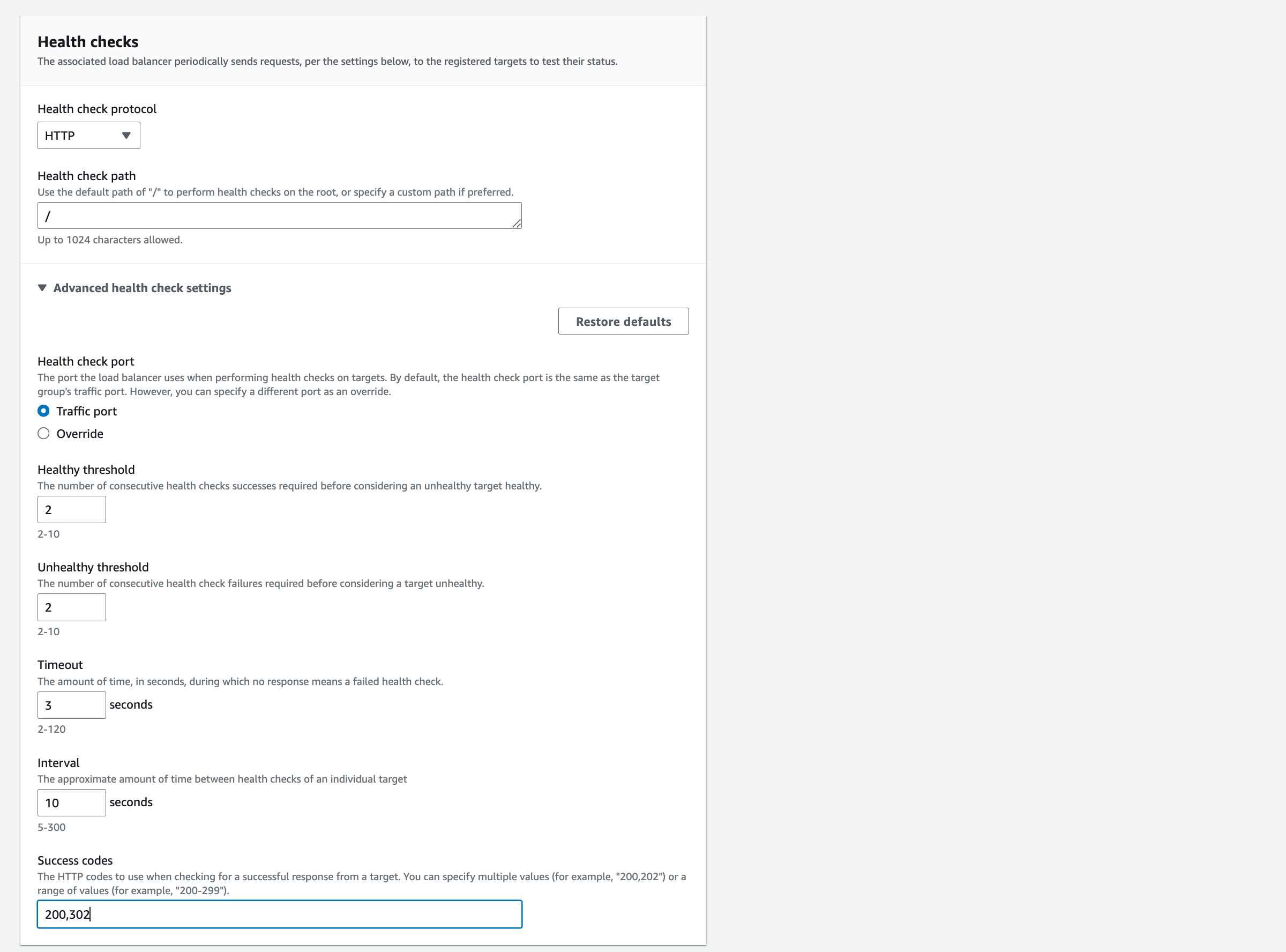
Click Next.
In this step select the checkbox next to the running instances you created in the previous section, then click ‘Include as pending below’.
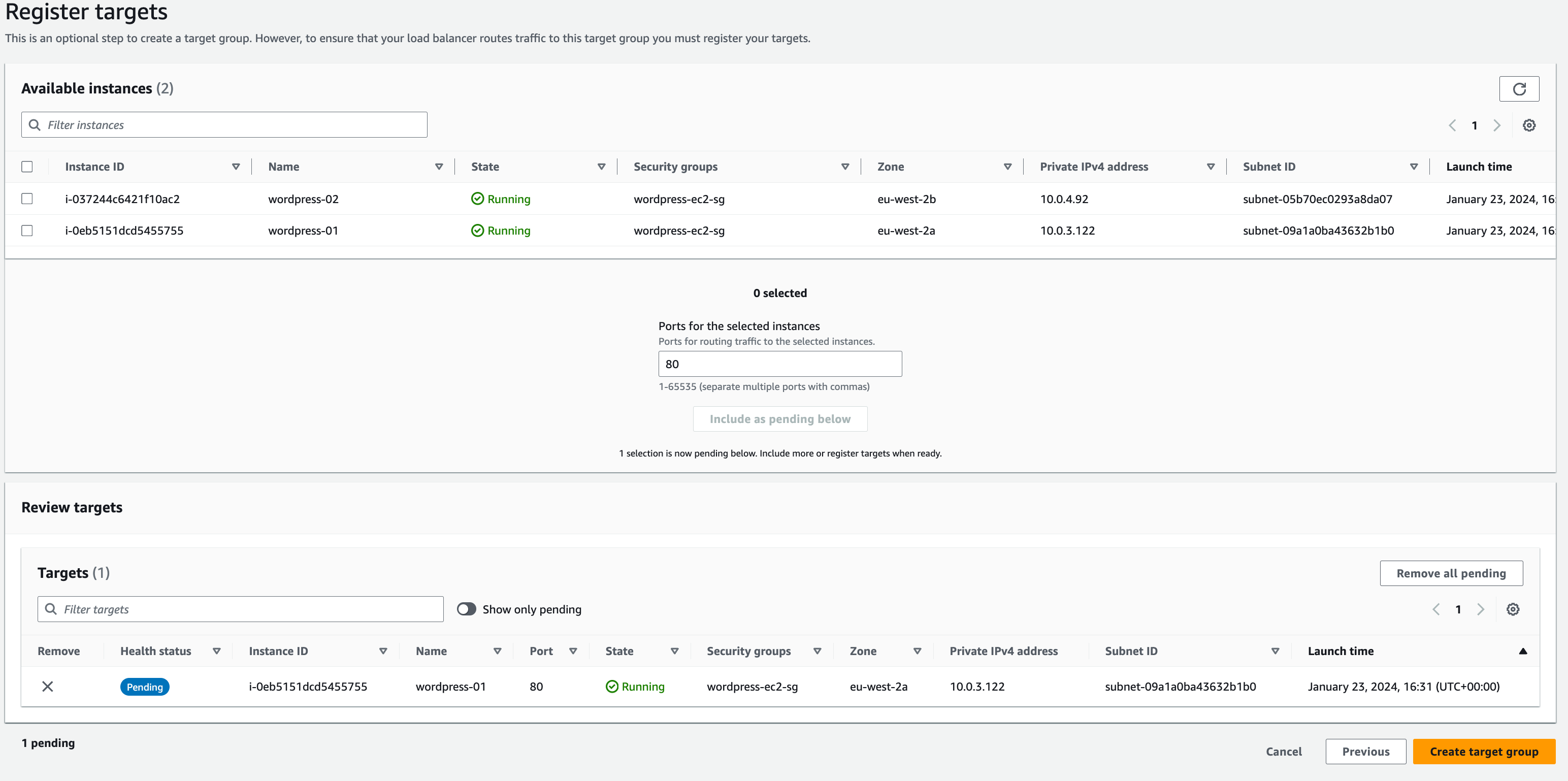
You will see the instance appear in the ‘Review targets’ section. press Create target group
Head back over to the previous tab where we were configuring our load balancer.
In the Listeners and routing section find the target group we just created in the drop-down menu. Don’t worry if it hasn’t appeared yet, you may just need to hit ‘refresh’.
Once you have done so, create the load balancer by pressing the orange button at the bottom of the page.
EC2 to Database connectivity
First, we will modify your Amazon RDS database to allow network access from your EC2 instance.
In the previous module, you created security group rules to allow HTTP and HTTPS traffic to your WordPress EC2 instance via the Load Balancer. The same principle applies here. This time, you want to allow certain traffic from your EC2 instance into your Amazon RDS database.
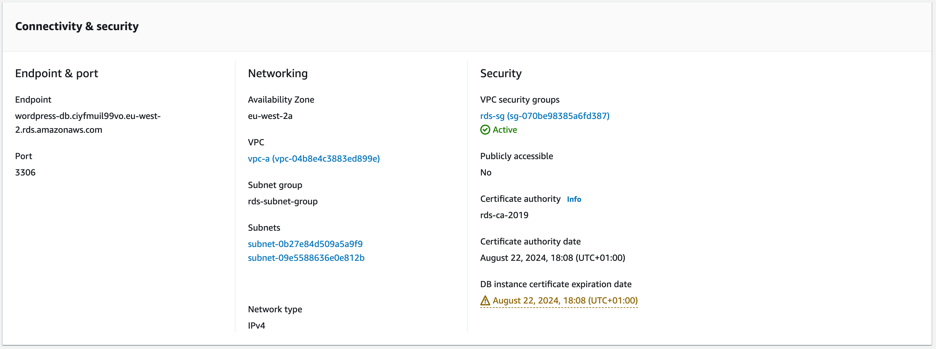
a. To configure this, go to the Amazon RDS databases page in the AWS console. Choose the MySQL database you created in the earlier module in this guide.
b. Click the Connectivity & security tab and choose the security group listed in VPC security groups. The console will take you to the security group configured for your database.
c. Select the Inbound rules tab – you should have the two rules previously configured. Click ‘Edit inbound rules’ and we will add access from the wordpress-ec2-sg .
Type: MYSQL/Aurora
Protocol and Port Range will be automatically updated
Source: custom then search ‘wordpress-ec2’ in the next box.
Description: sql-from-wordpress-ec2-sg
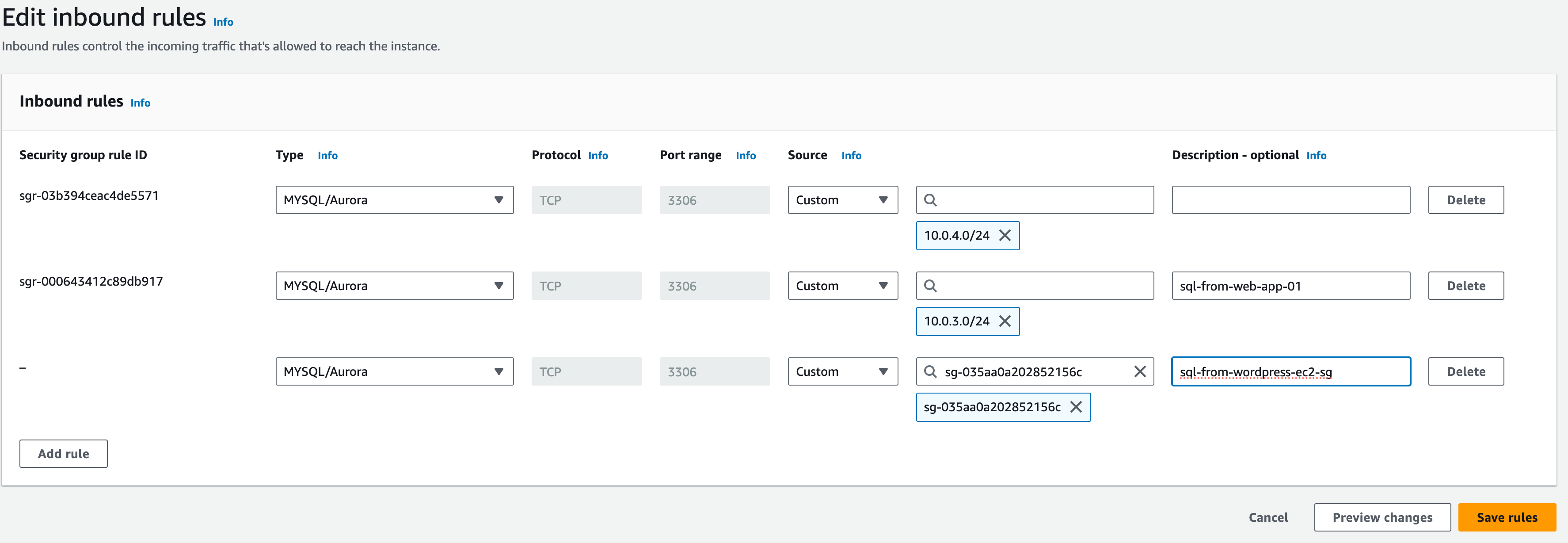
After you choose the wordpress-ec2-sg, the security group ID will be filled in. This rule will allow MySQL access to any EC2 instance with that security group configured.
Click ‘save rules’.
Connecting to the instance via Session Manager
Session Manager is a fully managed AWS Systems Manager capability. With Session Manager, you can manage your Amazon Elastic Compute Cloud (Amazon EC2) instances, edge devices, on-premises servers, and virtual machines (VMs).
In order to connect to our instances via session manager, we first need to add an IAM role for this capability.
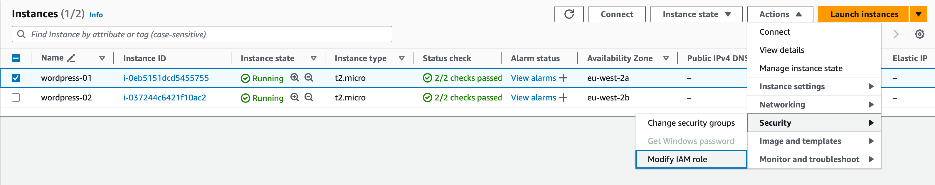
Select the first instance, then click Actions -> Security -> Modify IAM Role
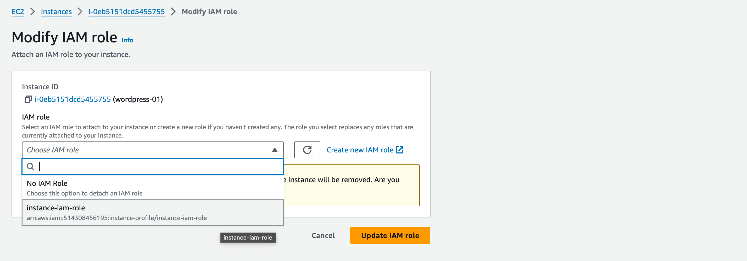
Select the AmazonSSMRoleForInstancesQuickSetup role, and click update IAM role.
Repeat the steps for the second instance.
It can take up to 30 minutes for the session manager to update the inventory with your instance. You should then be able to connect via the steps in the next lecture. However, if you are having issues, please reach out to your mentor, who will be able to assist you.
Mounting EFS to WordPress EC2 Instance
After we have successfully created the EFS, we now need to Mount the targets onto the EC2 instances.
1. From the console, select the newly created EFS, and click “attach”
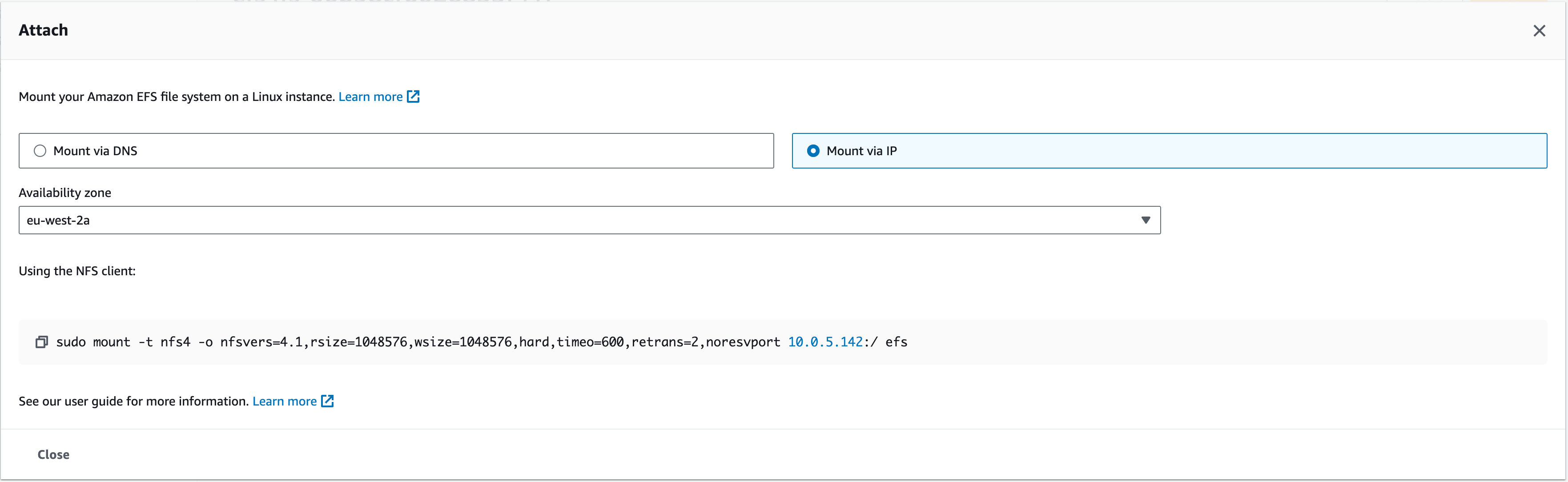
1.1. This should bring up a couple of selections; Mount via DNS, Mount via IP. For this workshop, we are going to Mount the EFS via IP using the NFS client we’re about to install on the Web APP instance.
Your command will look similar to this:
sudo mount -t nfs4 -o nfsvers=4.1,rsize=1048576,wsize=1048576,hard,timeo=600,retrans=2,noresvport 10.0.5.116:/ efs
2. In a new tab, connect to wordpress-01 EC2 via SSM. On the EC2 console page, under ‘Instances’, tick the box next to ‘wordpress-01’ and click ‘connect’. Even though our instance is in a private subnet without direct internet access, it can reach the internet through the load balancer we have configured.
3. We need to install the NFS client. NFS stands for Network File System which is the protocol that defines the way files are stored and retrieved from storage devices, in this case, EFS. The client enables this on the instance
4. Enter (copy and paste): sudo yum -y install nfs-utils

5. The ‘sudo’ at the start of the command above grants us root user privileges. We can put ‘sudo’ at the start of each command to run it as the root user. However, a more efficient way is to switch to automatically run every command as the root user.
Enter: sudo su – and you should see the root user id appear at the start of your command line.

5. Create a new directory for the EFS mount point by entering: mkdir efs
5.1. Now enter (to list the directories in this instance): ls
Which should show our newly created efs directory like the screenshot below:

6. Now we can run the command from step 1.1 in this section under Mount via IP (‘Using the NFS client:’) which will mount the EFS to the instance within this ‘efs’ directory we created
The instance should now have successfully mounted the target of the EFS
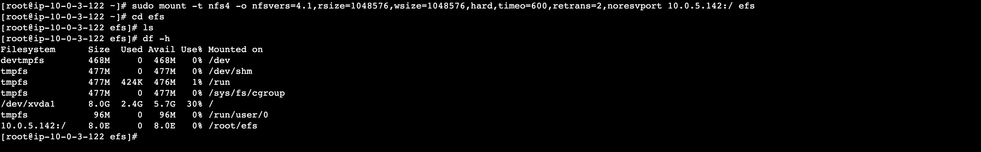
7. To test, we can navigate to the new directory and try to list all contents – it should appear empty. Enter:
cd efs
7.1. Then enter the ls command like part 5.1. It should list empty
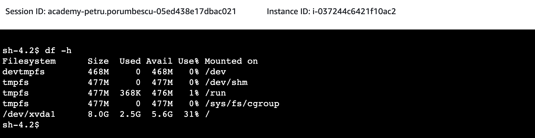
8. To test that EFS has mounted successfully to the instance, enter the command:
df -h
Which should list your attached EFS in this list (the last entry on the screenshot – 10.0.5.196, mounted on /root/efs)
Repeat the steps for the second instance.
Introduction
This section covers the Route 53 and Cloudfront services.
Route 53 is the AWS service for DNS. This week we configure the friendly names to access each part of the infrastructure we are deploying.
Amazon CloudFront is a Content Delivery Network service, providing access to a global infrastructure for caching your website content for quick access whilst reducing load on your backend systems.
The following diagram highlights the area of the architecture that is covered in red.
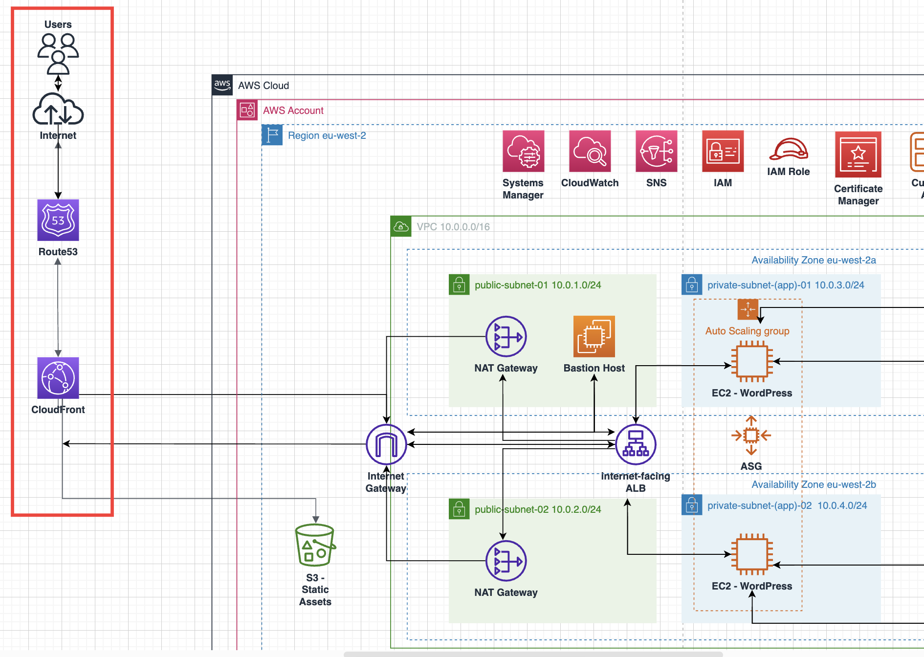
We are now going to build the components used to access your application from around the world. In the first section, we will be adding the friendly DNS names for each of the services, this is the Route 53 service. In the second section, we will configure the global caching service, CloudFront.
Route 53:
We will be creating public and private zones
Assigning records to the AWS services in the architecture, these will be:
EFS: storage.int.mobacademyworkshop.com
ElastiCache: cache.int.mobacademyworkshop.com
RDS Database: database.int.mobacademyworkshop.com
ALB: wp-lb.int.mobacademyworkshop.com
S3 bucket for Assets: assets.mobiliseacademy.com
CloudFront: www.<initials>.mobilise.academy
CloudFront:
We will configure CloudFront distribution for WordPress
We will point this distribution to the Application Load Balancer
Route53
Let’s begin by adding in the private DNS zone. Log in to your AWS account as you have done in previous weeks.
- On the search bar, type in Route 53 and click on the services entry to access the service
- On the left-hand menu, click on Hosted zones
- In this console, click on Create hosted zone to begin the process
- On the wizard to create a DNS zone, enter the following parameters:
1. Domain name: int.mobilise.academy
2. Description: Internal DNS zone for friendly resource names
3. Type: Private hosted zone
4. Region: Europe (London) [eu-west-2]
5. VPC ID: select the VPC ID that shows up for your deployed resources
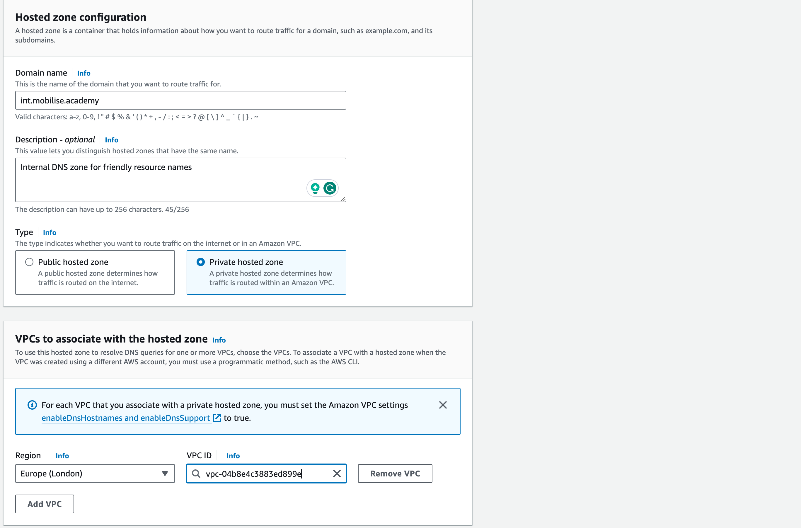
5. Once the above information is entered correctly, click on Create hosted zone at the bottom of the page
To create the first entry for the EFS storage, click on Create record and use the following information to complete the records to be used
Record name: storage
Record type: CNAME
- Value: the DNS name for the EFS storage configured, e.g. fs-0123456789.efs.eu-west-2.amazonaws.com
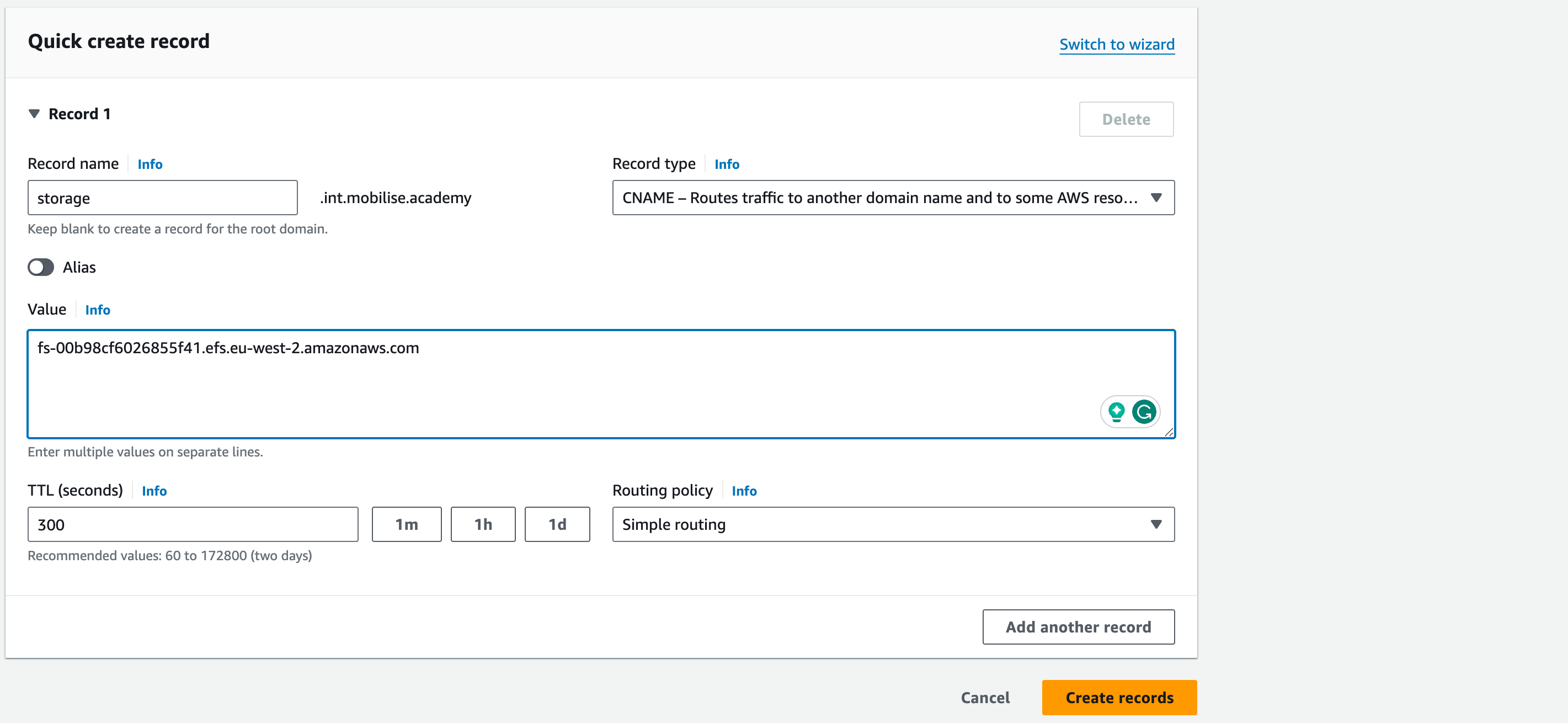
6. Leave all other setting as-is and click Add another record
7. Now to create the RDS database entry, use the following information
- Record name: database
- Record type: CNAME
- Value: the DNS name for the wordpress-db endpoint, e.g. wordpress-db.cqd25we3rgk.eu-west-2.rds.amazonaws.com
- Again, leave the remaining entries as-is and click Add another record
8. Now to create the ElastiCache entry, use the following information
- Record name: cache
- Record type: CNAME
- Value: the DNS name for the Memcached cluster configuration endpoint, e.g. memcached-cluster.17p9iv.cfg.euw2.cache.amazonaws.com:11211
10. Again, leave the remaining entries as-is and click Add another record
11. Now to create the ALB entry, use the following information
Record name: wp-lb
Record type: A
‘Value’: click the button to enable ‘alias’, then the subheading ‘value’ will change to ‘Route traffic to’.
First drop-down: select Alias to Application and Classic Load Balancer
Second drop-down: select the region with the ALB
Third drop-down: select the ALB
12. Leave all other settings as-is and click Create records
13. All internal DNS records have now been created and we will configure public DNS zone and entries
14. Back in the Route 53 console homepage, Click Create hosted zone to create the public zone. Set the Domain Name as follows:
<your initials>.mobilise.academy, i.e. mob.mobilise.academy
15. Leave the Type as Public hosted zone and click Create hosted zone
16. You will now see the zone is created and be presented with the initial entries for a new DNS zone.
17. Expand the Hosted zone details section and make a note of the Name servers list, this needs to be provided to the instructors so we can create the delegation for your DNS zone to be accessible over the Internet, please provide:
Public DNS Zone Name: i.e. <inits>.mobilise.academy
Name server assigned to your public DNS zone
18. Now, we need to create the entries to make your application accessible
19. Leave all other settings as-is and click Create Record
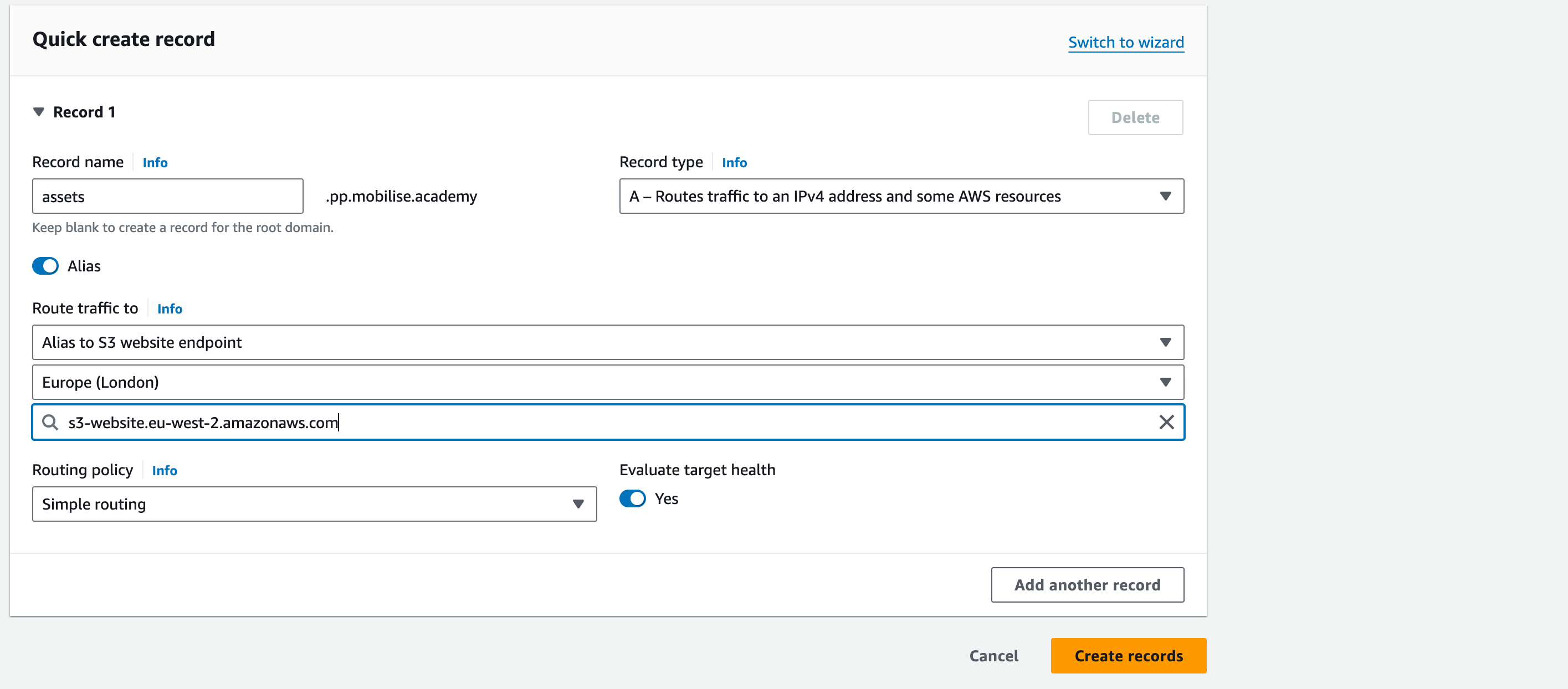
20. Now, to create the assets S3 bucket entry, click Create Record and use the following information
Record name: assets
Record type: A
Route traffic to: click on alias
First drop-down: select Alias to S3 website endpoint
Second drop-down: select the region with the S3 bucket
Third drop-down: select the S3 bucket that has been enabled for web hosting
21. Leave all other settings as-is and click Create records
22. The final DNS entry to be created is for the CloudFront distribution, however until it is deployed, we cannot create this so will come back at the end of the next section to create that record
CloudFront
Now our services have a way of finding each other using some friendly DNS names, we can finally add in the global caching service and make the WordPress platform available for everyone.
Do not forget, we are currently missing one DNS entry and that is the friendly name for the CloudFront service which we are about to deploy. We will also be configuring a secure certificate for CloudFront to allow users to log in securely.
- Search for cloudfront into the service search bar and click on the entry shown
2. To create our distribution, click on Create a CloudFront distribution
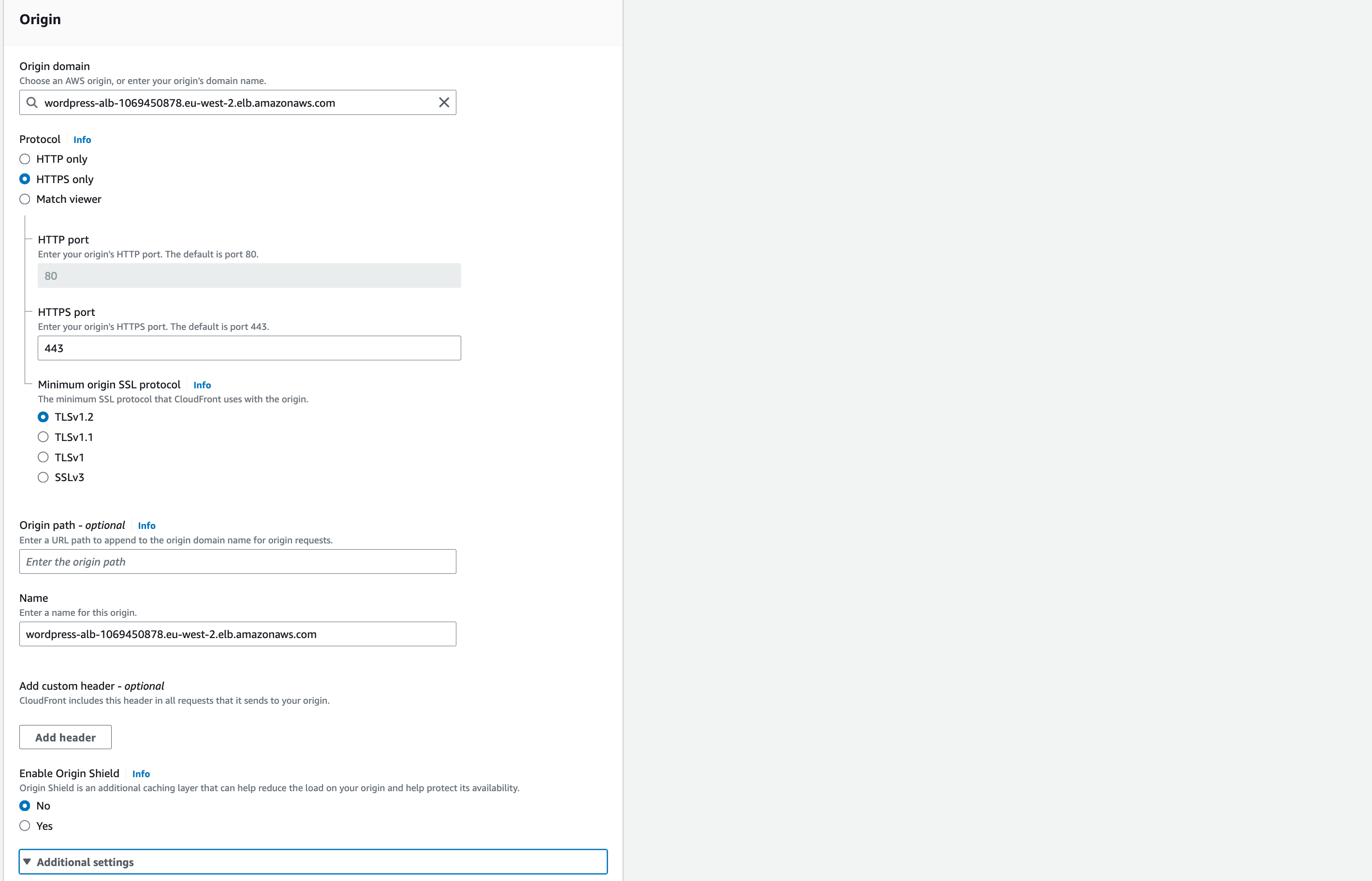
On the wizard page, use the following settings to configure CloudFront
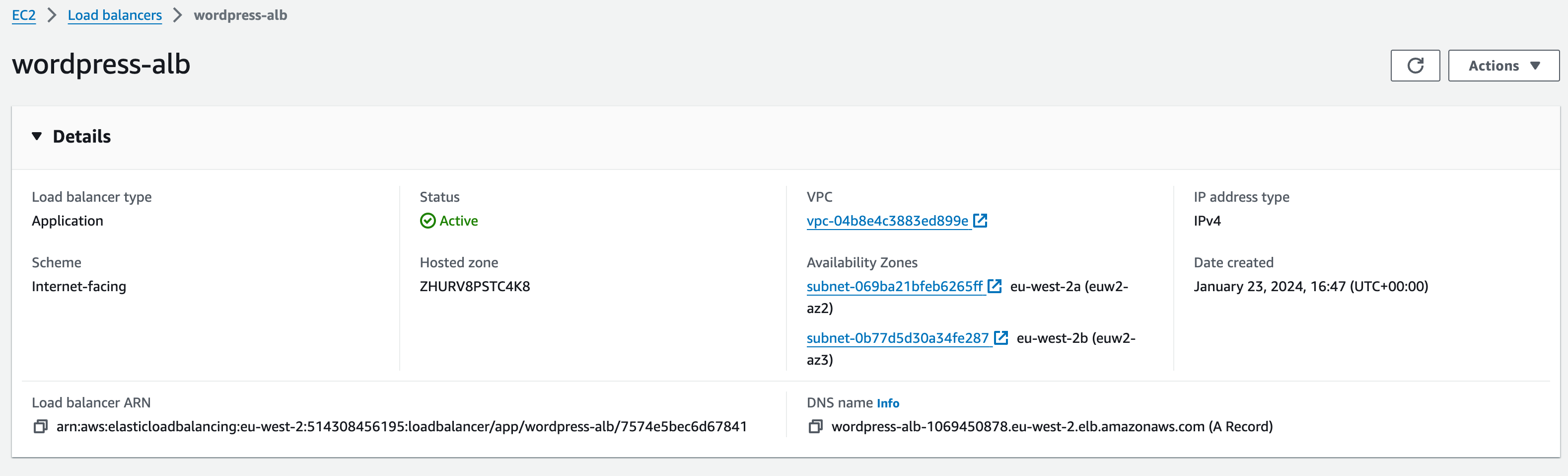
Origin domain name: this needs to be the DNS name for the ALB, e.g. www-lb.<inits>.mobilise.academy
Protocol: HTTP only
HTTP Port: 80 (should automatically appear)
Origin Path: leave blank
Name: keep as default
Enable Origin Shield: leave as default (‘no’)
Additional settings – leave as default
Default Cache Behaviour:
Path pattern: default
Compress objects automatically: yes (default)
Under Viewer –> Viewer protocol policy: redirect HTTP to HTTPS
10. Allowed HTTP methods: select GET, HEAD, OPTIONS, PUT, POST, PATCH, DELETE
11. Under Cache HTTP methods, tick the box next to OPTIONS
12. Leave Restrict viewer access as ‘no’
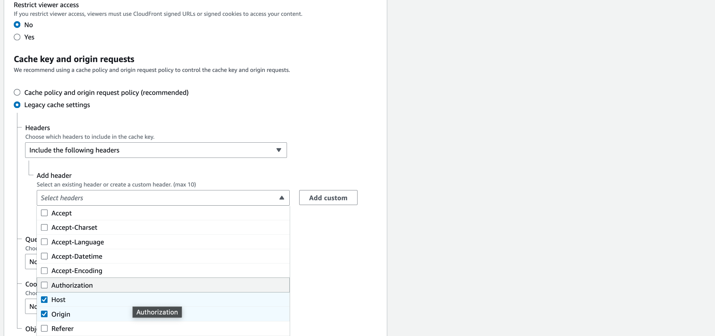
13. In the section titled Cache key and origin requests, select the option for Legacy cache settings
14. Under Headers, in the drop-down select the option for Include the following headers
15. In the Add header drop-down, find and select Host and Origin.
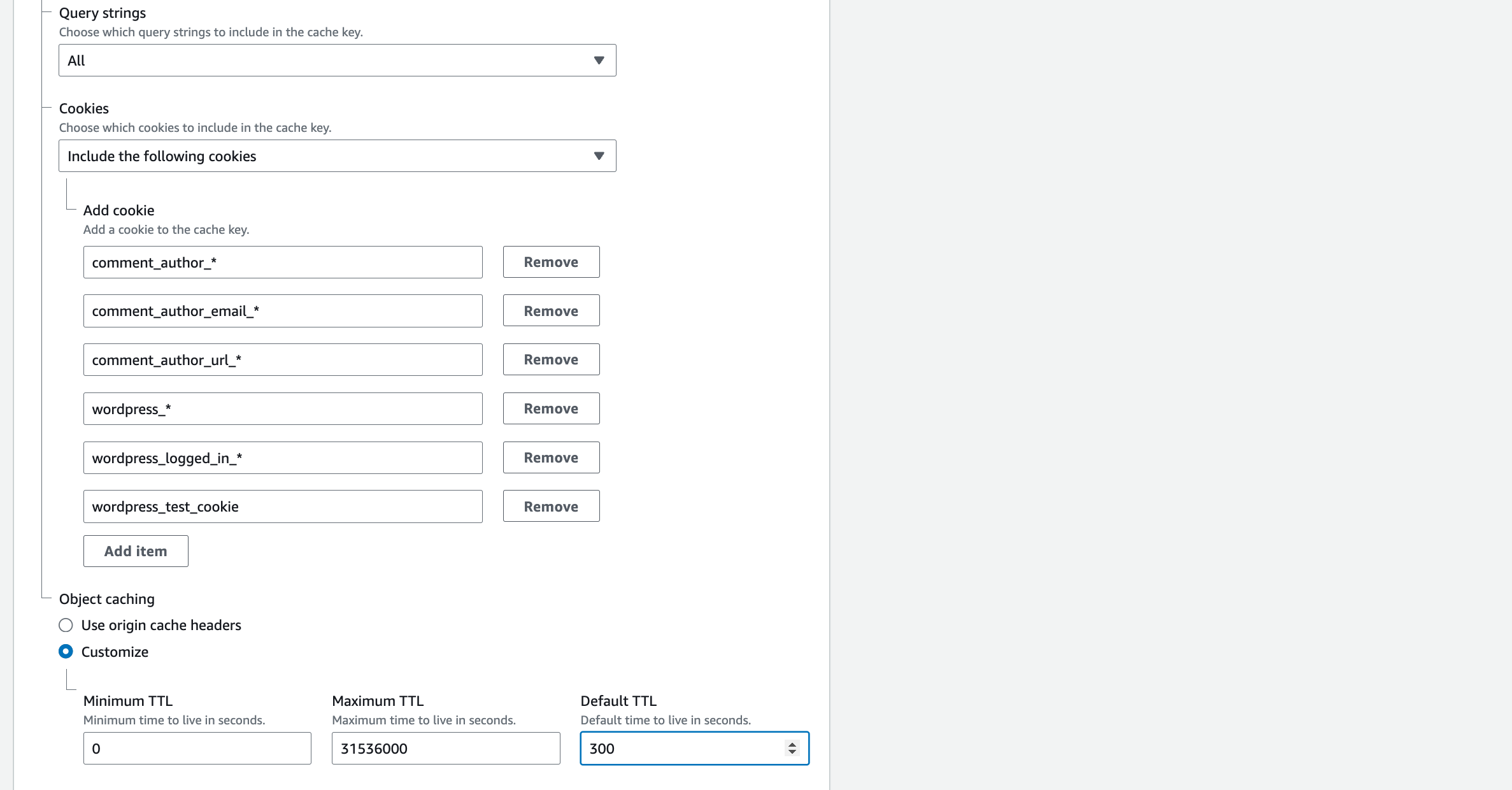
16. Query strings: All
17. Cookies: Include the following cookies
18. In Allow: enter the name of each of these cookies, clicking ‘add item’ after each one:
comment_author_*
comment_author_email_*
comment_author_url_*
wordpress_*
wordpress_logged_in_*
wordpress_test_cookie
19. Object caching: Customise: Set Default TTL to 300
20. Function associations: leave as default
21. Settings: Alternate domain name (CNAME) –> Add item –> enter: www.<yourinitials>.mobilise.academy
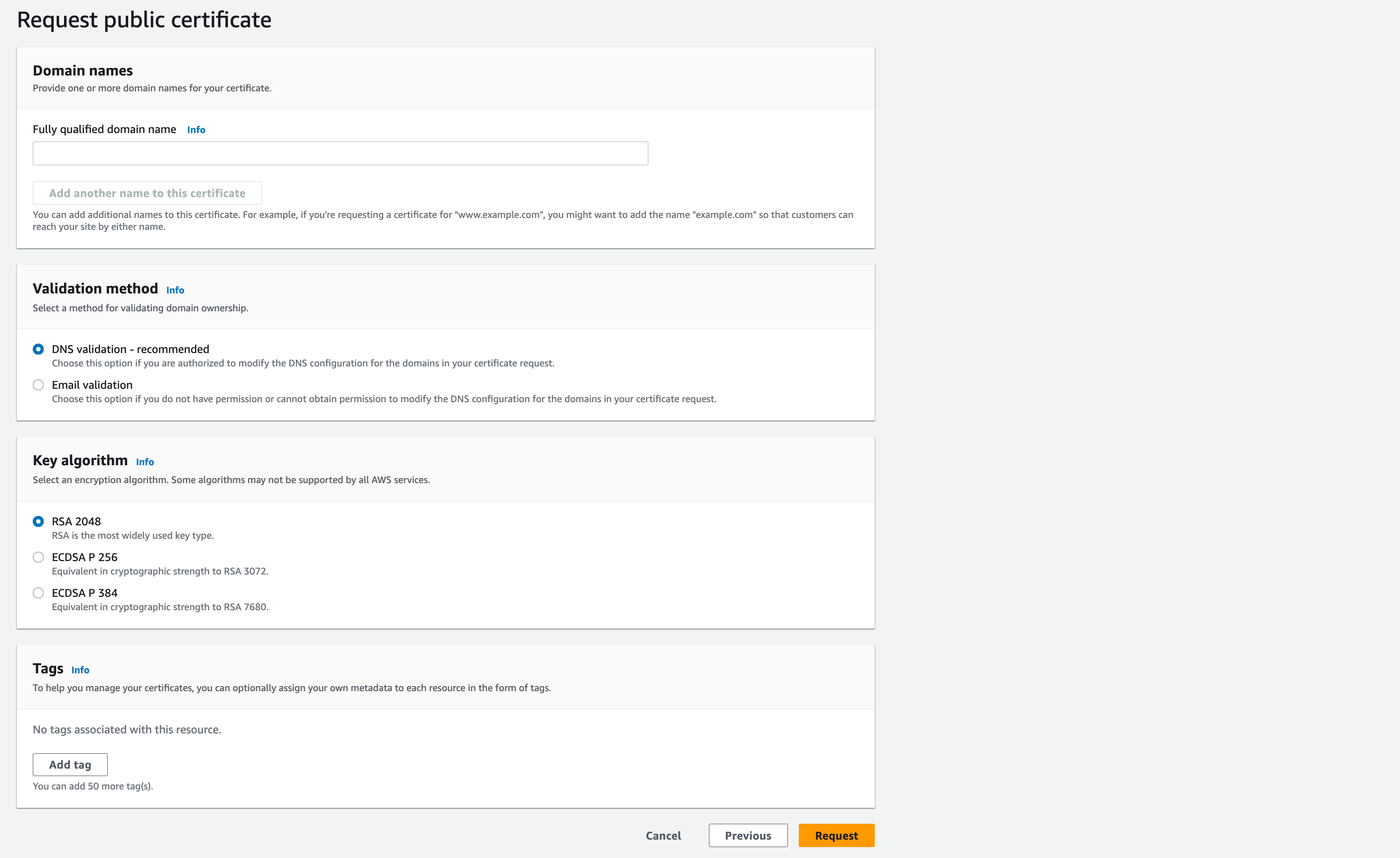
22. Custom SSL Certificate: click Request certificate
23. This will take you to the ACM service in a new tab to get a free Amazon certificate for CloudFront, on this page select the following
24. Fully qualified domain name: www.<inits>.mobilise.academy (NB I have used ‘mobiliseacademyrs’ as the prefix, you can just use your initials).
25. You can also click add another name and enter your website without ‘www.’, e.g. <inits>.mobilise.academy
DNS Validation: leave this selected
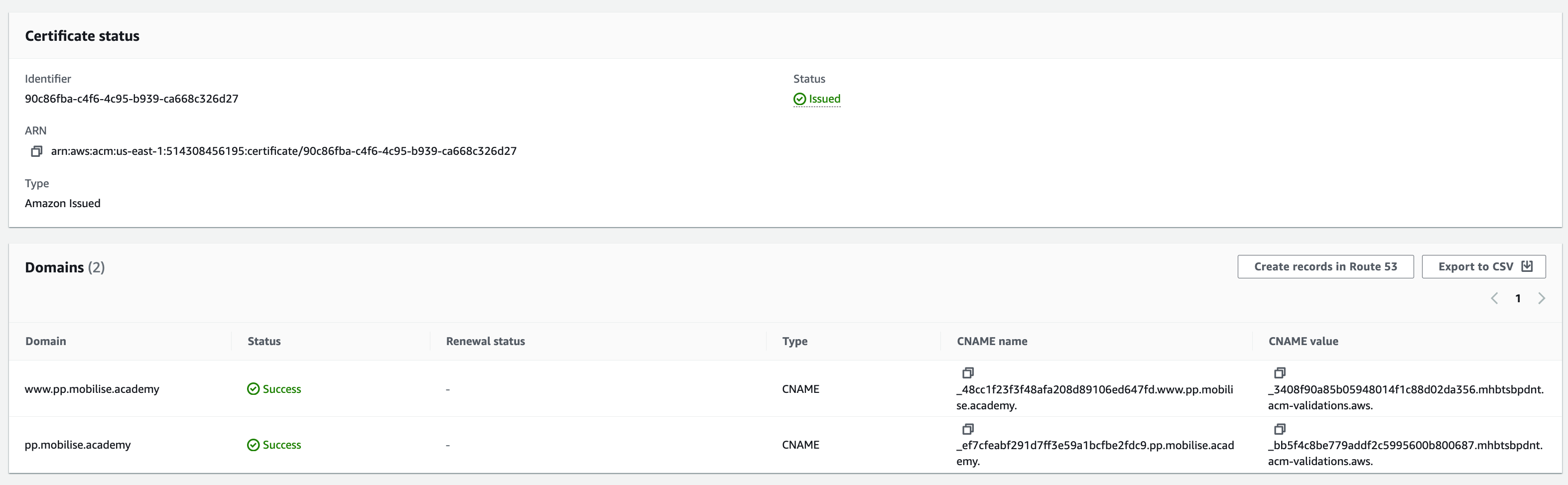
27. Click Request to generate the certificate request, if the request does not show in the console, click the refresh button
28. Select the certificate request which should show a Pending validation
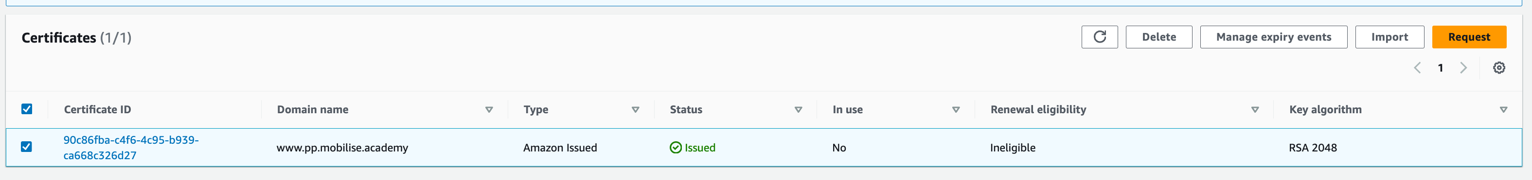
29. Select the option to Create records in Route 53 to allow the required DNS entries to be automatically created for you, once this is done it should only be a short time before the certificate changes to Issued
30. Once validated and issued, return to the wizard for the cloudfront distribution and click the refresh button next to the Custom SSL certificate drop-down, this should refresh the list and allow you to select the certificate created
31. Finally, click Create distribution at the bottom of the page
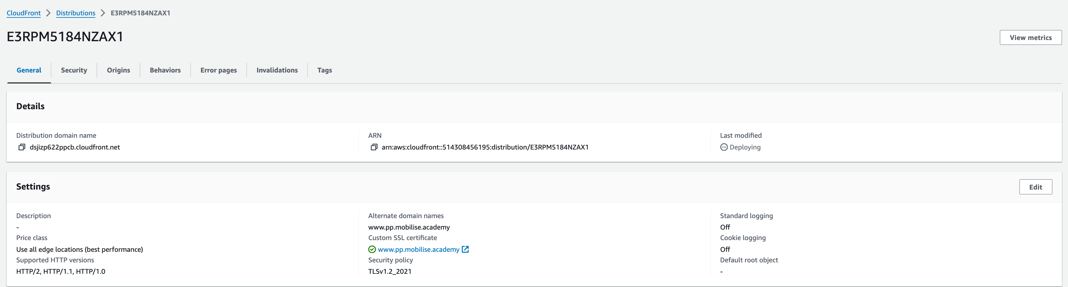
This can take some time, typically in the region of 10-15 minutes
Finally, we need to register the friendly name of the cloudfront distribution in Route 53
Return to the Route 53 service, select the public zone and click Create record
In the Record name field, enter www
Record Type A
Select the alias button and in the first drop-down, route traffic to Alias to CloudFront distribution
The second drop-down will automatically select US East (N. Virginia) as although CloudFront distributions are considered ‘Global’ resources, they are technically all created in this region.
In the third drop-down, select the CloudFront distribution created earlier and click Create records
If the CloudFront distribution isn’t listed here, AWS do some verification in the background, so make sure the alias on the CloudFront distribution matches the domain name being entered exactly.
Once complete, your website should now be accessible using the http://www.<inits>.mobilise.academy/ address in your browser. (Note: This may take a few minutes)
WordPress Website Access
Once complete, your website should now be accessible in two ways:
1. via the Load Balancer.
Navigate back to your load balancer. Copy the DNS name and paste it into a web browser. This should bring up the WordPress installation page.
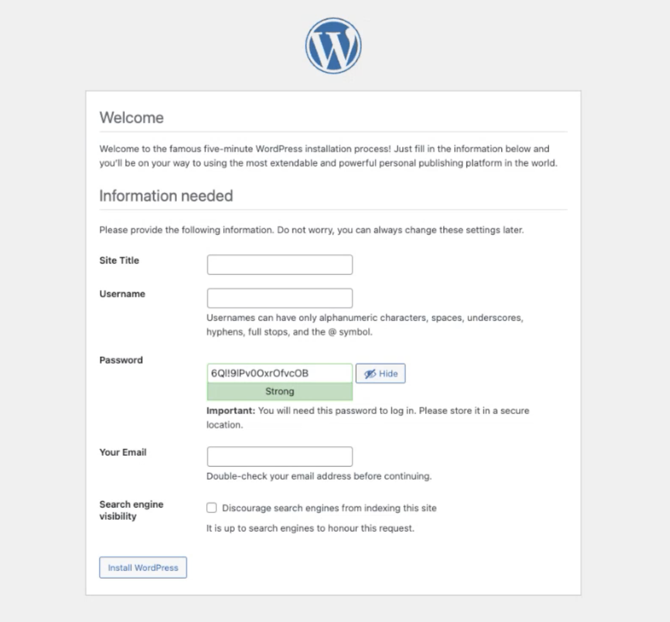
Type in your username (you_user_name), password (Your_password123) and enter your email. You should only need to log in once.
Once complete and you’ve logged in, your website should now be accessible using the http://www.<inits>.mobilise.academy/ address in your browser. (NB: This may take a few minutes. If you experience any issues accessing the site then ensure you have included the ‘www’ at the start).
If you are still unable to access your site then work back through the lectures and check everything is configured correctly. You can also ask a colleague at Mobilise for any help required.
Objectives
In this section, we will be increasing the HA capability of the WordPress application by performing the following on each AWS component:
WordPress Instance:
Creating an Amazon Machine Image (AMI) of our current EC2 instances.
WordPress Load Balancer:
Creating a Launch Template using our WordPress AMI.
Configuring an Auto Scaling Group for our WordPress deployment, spanning separate Availability Zones.
HA Testing:
Test failure of a WordPress instance and how Auto Scaling reacts.
Updating EFS Mount Config
In section 5, we mounted the EFS volume to the WordPress-01 instance. This week, we’ll be taking an AMI of this instance, which will cause the EFS to unmount unless we make an update to the /etc/fstab file (file systems table file) within the instance’s system configuration files.
- Connect to the WordPress-01 instance via SSM.
2. Check the EFS is still mounted to your instance using:
df -hIf it’s not, use the instructions from the ‘Databases and Storage’ section to remount EFS before moving onto the next stage.
3. To make ‘write’ changes to this file, we need to edit as root user: Enter
sudo su –
You should see the user change from ‘sh-4.2$’ or similar, to ‘root@ip-10.x.x.x.’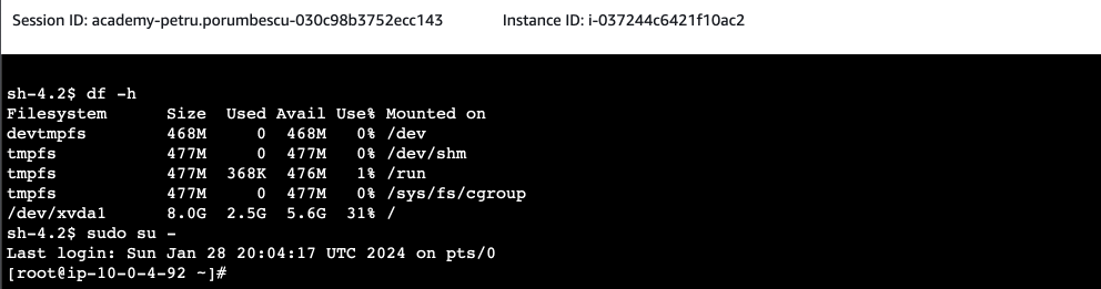
4. To access and edit the /etc/fstab file, enter:
vim /etc/fstab
5. You should now see the file name at the bottom left-hand corner and a series of lines/hyphens going down the file (the space for editing and adding lines of code)
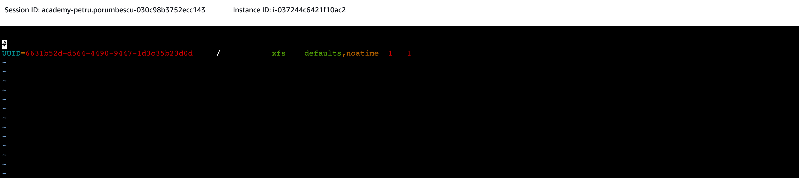
To edit the file enter:
i. You should see ‘– INSERT –‘ appear at the bottom of your file. This means you are now in ‘Insert’ mode and you can edit the file. Use the up/down/left/right arrow keys to navigate the file. To add text, type or copy it in. To remove text, use the backspace key.Copy the following into a text editor (e.g. notepad, TextEdit, Word) file:
file_system_id. aws_region.amazonaws.com:/ mount_point / efs nfs4 nfsvers=4.1,rsize=1048576,wsize=1048576,hard,timeo=600,retrans=2,noresvport,_netdev 0 0
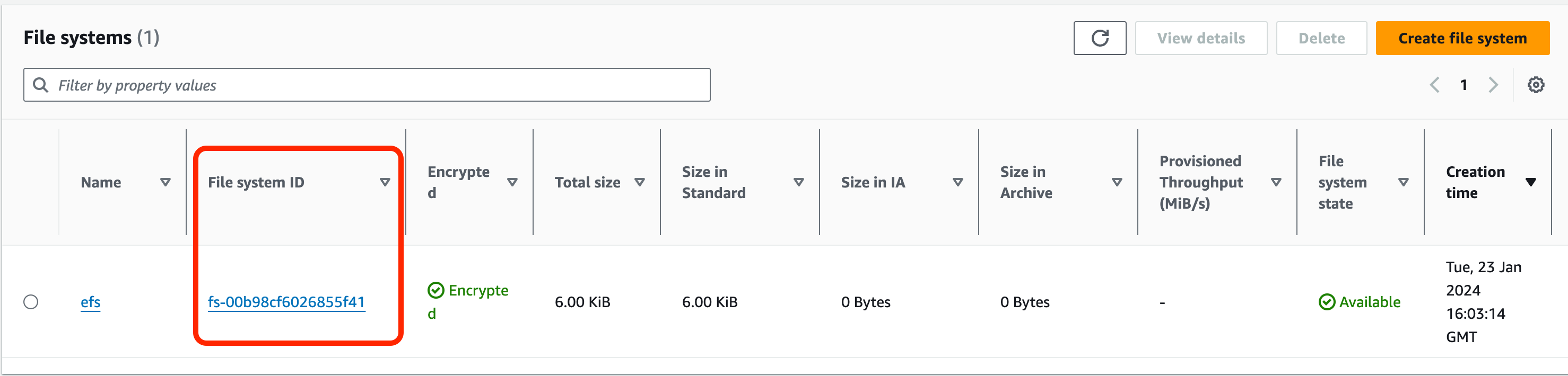
In the line of code, replace the variables listed below as follows:file_system_id= find this value on the console under ‘File Systems’ within the EFS service

aws_region = eu-west-2mount_point = /efs (ensure there is a space between this and the ‘:/’
Press ‘enter’ to create a new line under the ‘#’ symbol, then paste in your SSM session in the terminal, on a new line.
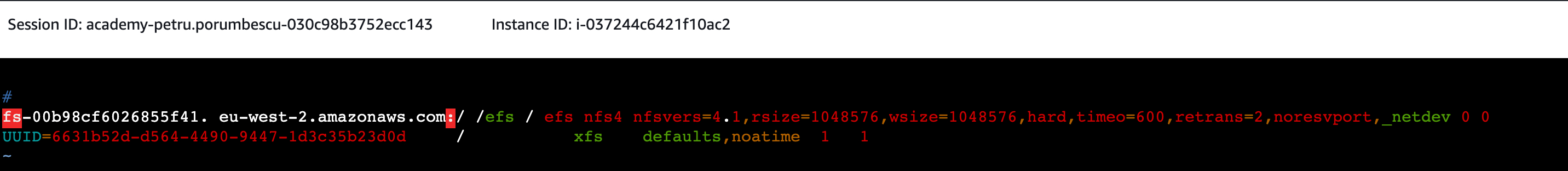
Leave ‘Insert’ mode by pressing ‘esc’. Save your changes and exit by pressing the ‘esc’ key. You should see ‘Insert’ disappear from the terminal. Now type
:x!or:wqfollowed by ‘enter’. This should leave the vim editor and return you to the terminal.You can now exit the SSM session – click ‘Terminate’ at the top right-hand of the terminal session.
Configure High Availability (HA) for WordPress EC2
In section 2, we will be focusing our attention on making our WordPress EC2 instance Highly Available as per the diagram below.
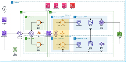
To achieve this will require:
- Amazon Machine Image (AMI) of the existing, configured WordPress instance.
- Launch Template.
- Auto Scaling Group (attached to the existing ALB).
Create WordPress AMI
In this section, we will create an image of the WordPress EC2 so that it can be used to create new instances as part of an Auto Scaling Group. In the AWS console, navigate to EC2.
- Select Instances.
- Select the WordPress-01 EC2 instance.
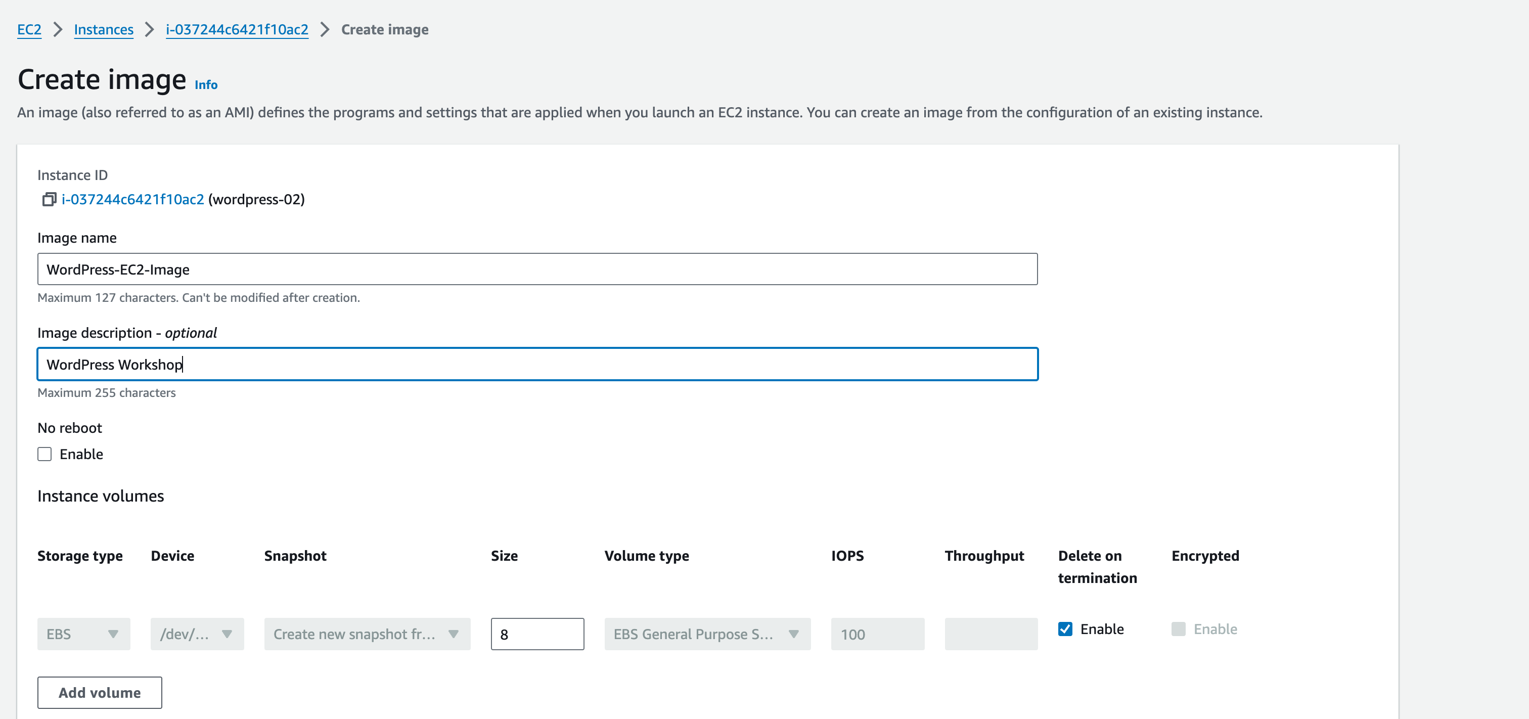
- Select Actions, then Image and templates and then Create image.
- Image name: WordPress-EC2-Image
- Image description: WordPress Workshop
Select Create image.
This will create an Amazon Machine Image (AMI). In EC2 console, navigate on the left pane to Images –> AMIs.
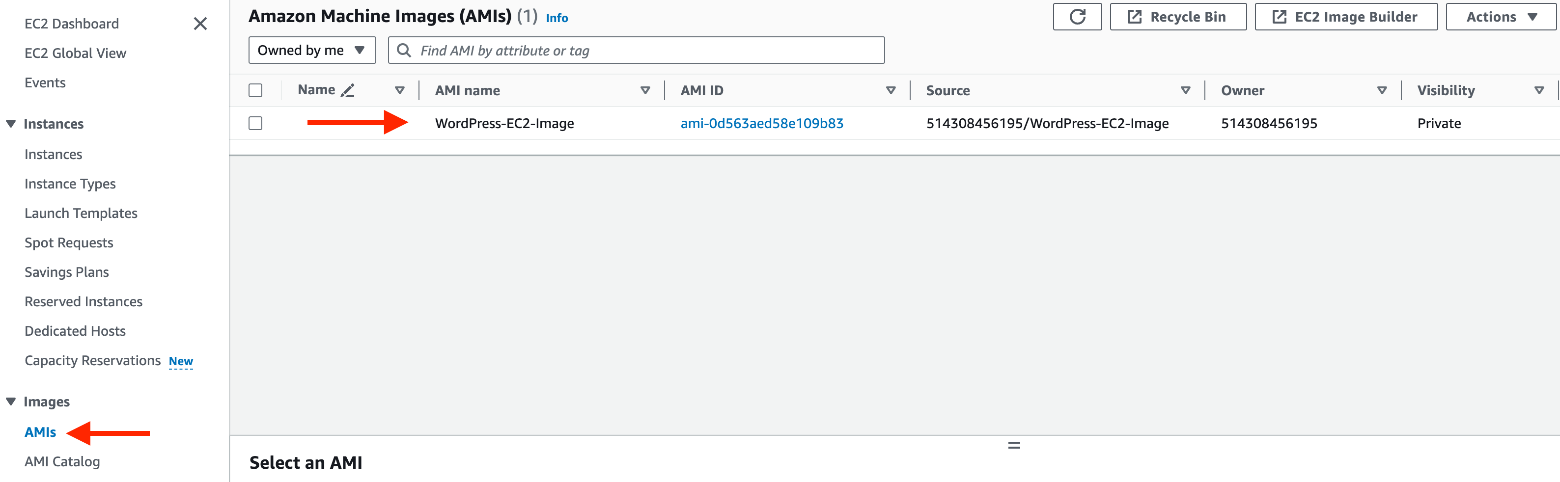
Here, you can tick the box next to your image and view the details of your image under the Details tab.
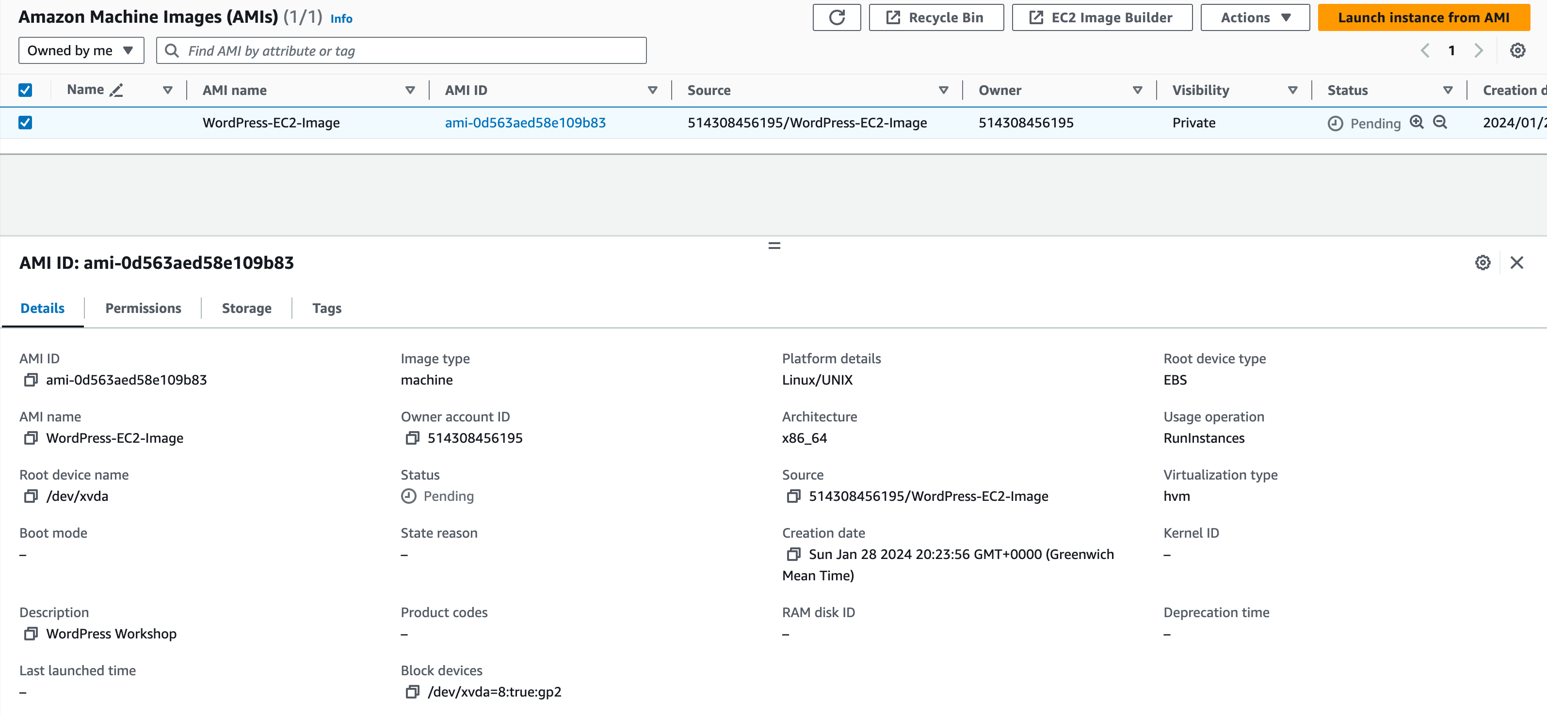
Make a note of the AMI ID for future reference.
Test Image
In this section, we will launch an EC2 from the AMI to verify that it is configured as expected.
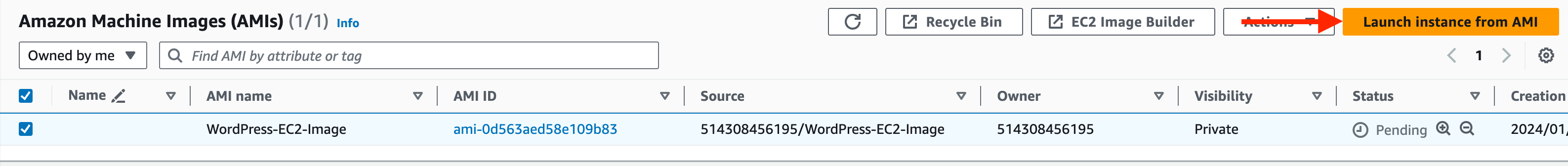
In the EC2 console, navigate to Images and AMIs.
Select the AMI previously created – you can filter by the image name if required (type “AMI name = “Wordpress-EC2-image” in the search box).
Select Launch instance from AMI.
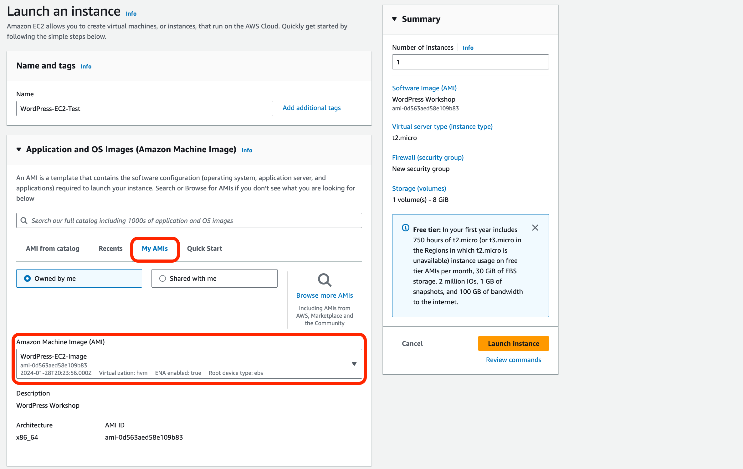
Use the following details for the temporary EC2 instance:
- Name: WordPress-EC2-Test
- Application and OS Images (Amazon Machine Image): Select the ‘My AMIs’ tab, check that your ‘WordPress-EC2-Image’ AMI is selected in the drop-down box.
- Instance Type: t2.micro.
- Key Pair: select the existing key pair you created earlier.
Under the Network Settings:
- Select Edit.
- VPC: Use the same VPC as the existing WordPress EC2 instance (‘should be VPC-A‘)
- Subnet: Private Subnet (APP) 01
- Auto-assign public IP: Disable (we will access via SSM).
- Select Existing Security Group: WordPress-EC2-SG.
- In the Summary box under Number of Instances, ensure 1 is set.
Confirm the settings in the Summary and click Launch Instance.
An EC2 instance will be created – once complete, log on and verify the settings
1. Access via the EC2 via SSM, it might take a while to work. If it’s not connecting check the box next to your instance and click Action, under that click Security and then Modify IAM Role. Ensure that the AmazonSSMRoleForInstancesQuickSetup is selected and click Update IAM Role.
2. Connect to your instance via Sessions Manager, again this could take 10 minutes.
3. Once in the Terminal, you will first need to verify that the httpd service is available and running. Type the following into the terminal:
sudo service httpd status
If the status has returned dead you can start the service via typing
sudo service httpd start
sudo service httpd status
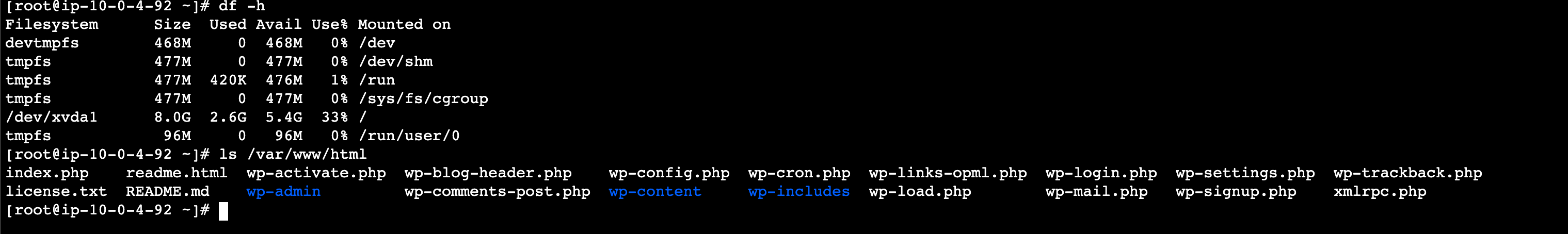
4. Then Type the following into the terminal to check that the EFS is mounted:
sudo su -
df -h
5. If the EFS is mounted correctly, the EC2 instance should show the WordPress config files when you run this command:
ls /var/www/html
6. If the files are available, the image is ready to be used as part of a Launch Template used by an Auto Scaling Group.
Create WordPress Launch Template
From the Management Console head over to the EC2 console. Then navigate to Instances –> Launch Templates.
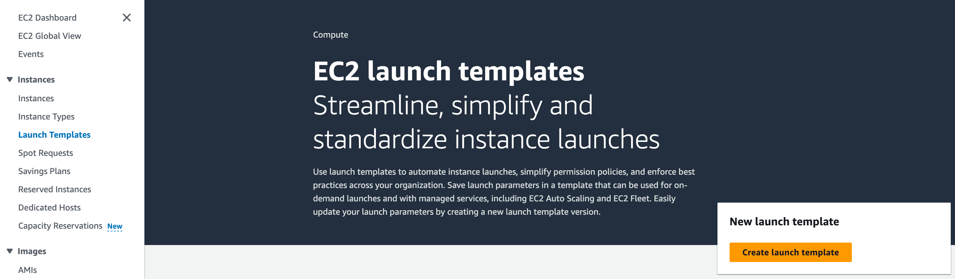
Click Create launch template.
Then we’ll be adding in details for our launch template:
- Launch template name and description:
Name: wordpress-launch-template.
Description: Launch Template for WordPress EC2 Instances.
2. Under Application and OS images (Amazon Machine Image).
Click Quick Start and then Select Browse more AMIs.
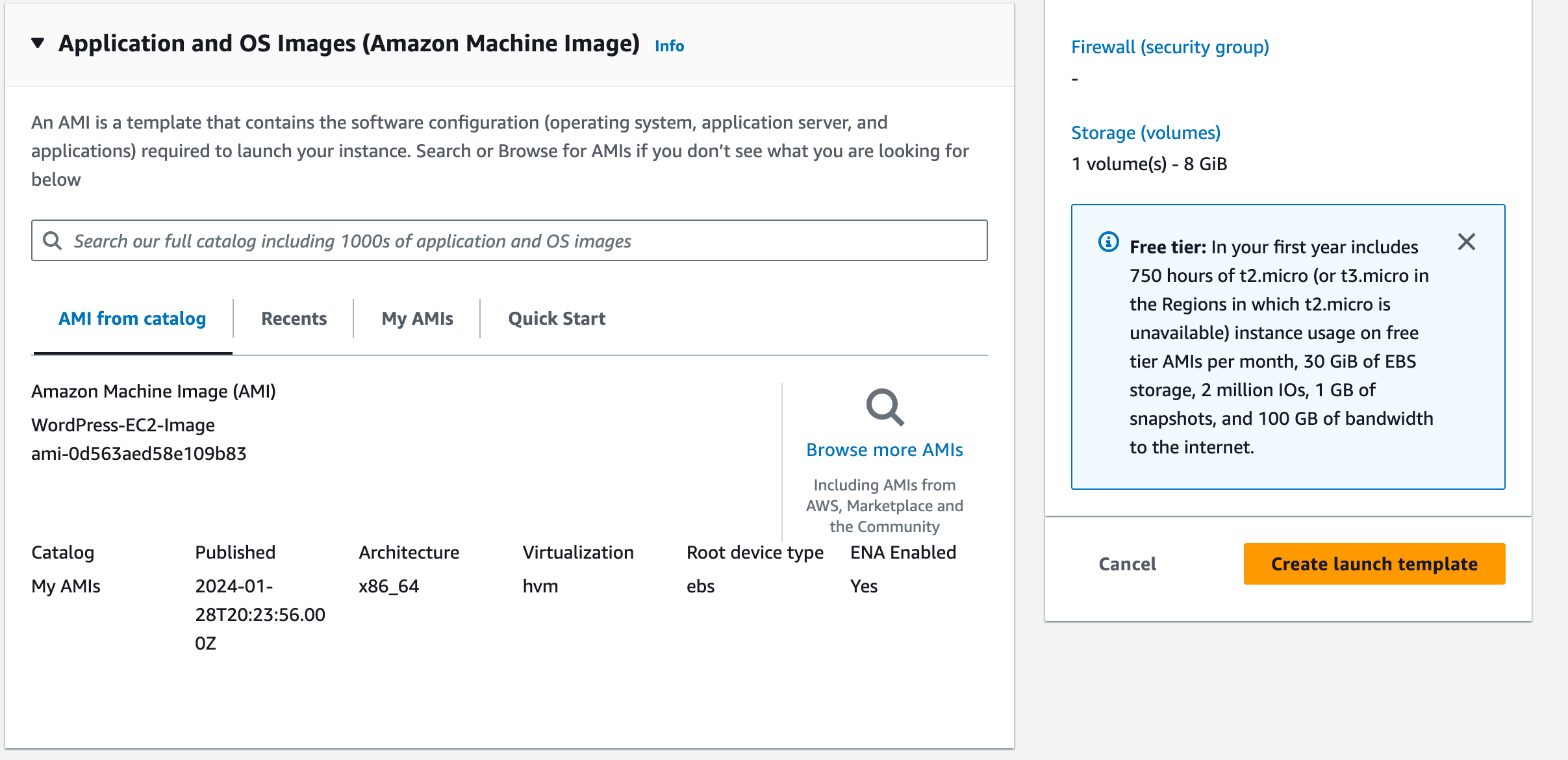
Select My AMIs.
Select the WordPress-EC2-Image AMI you previously created.
3. Instance type:
Under the dropdown, select ‘t2.micro’.
4. Key Pair (login):
Choose an existing key pair –> (e.g. ‘mobilise-ec2-key-pair’). Select the checkbox to acknowledge that you have access to the private key.
5. Network Settings:
Subnet: Don’t include in launch template.
Security groups: Choose the WordPress EC2 Security Group (e.g. ‘WordPress-EC2-SG‘) that you’ve used for your other instances.
6. Resource Tags:
7. Advanced details:
Add IAM instance profile “AmazonSSMRoleForInstancesQuickSetup“
Note: For production type workloads, we would typically enable a few additional options (such as instance monitoring within CloudWatch), but we can skip these as part of this workshop.
Review Summary and then click Create launch template.
Your launch template should now be visible within the console.
Configure Auto Scaling
1. In the EC2 console, navigate to Auto Scaling then Auto Scaling Groups.
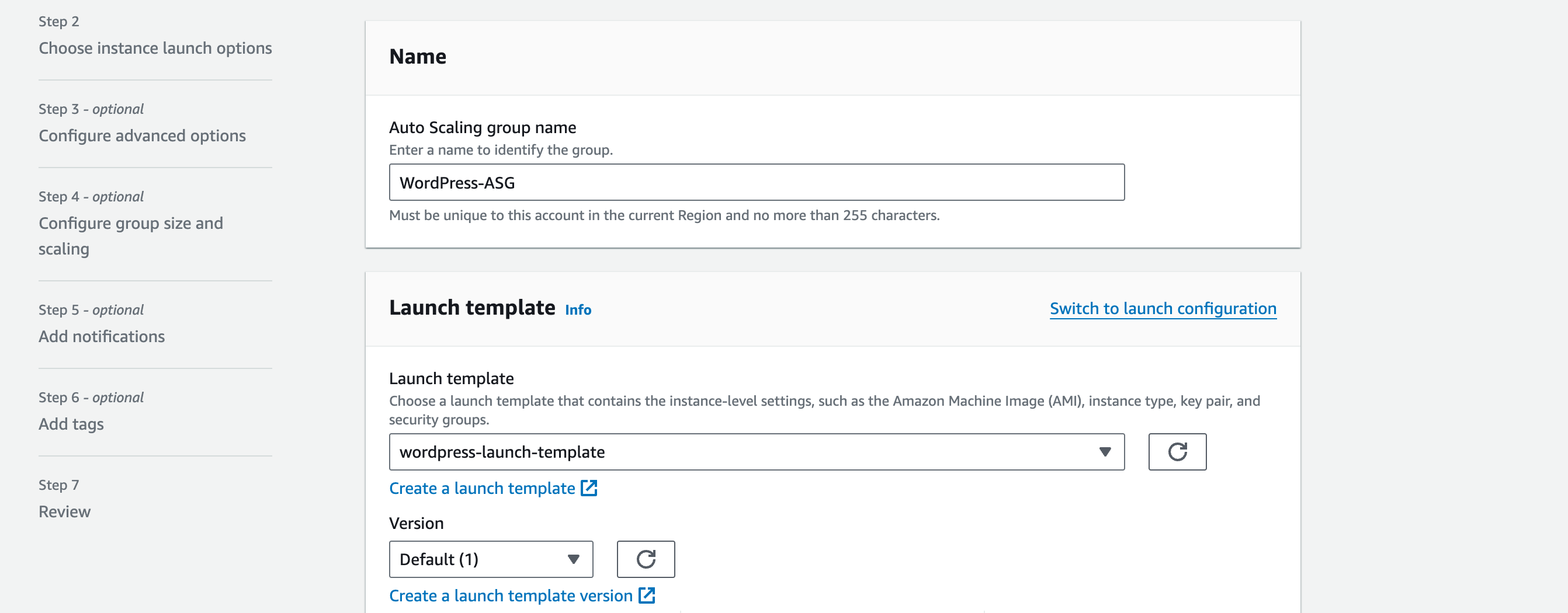
a. Click Create Auto Scaling Group
b. Name: WordPress-ASG
c. On the launch template dropdown, select the launch template we created in the previous section.
Double-check that the details are correct and select Next.
Under Network, select the VPC and Availability Zones & subnets:
i. VPC: VPC A.
ii. Availability Zones and subnets: Private Subnet (APP) 01 and Private Subnet (APP) 02
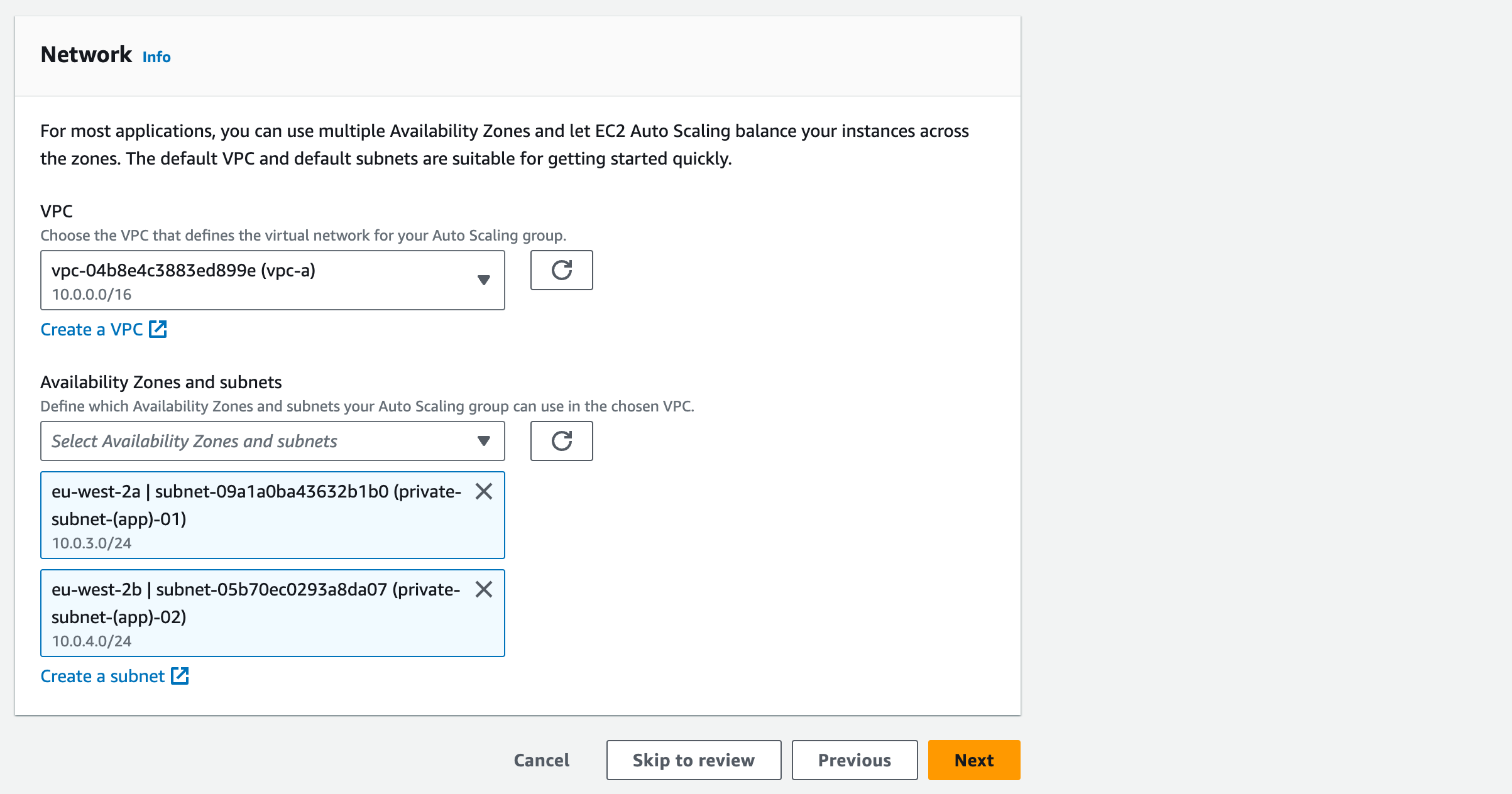
iii. This defines where the Auto Scaling Group can deploy new EC2 instances. By selecting multiple subnets, we can spread the EC2 instances for HA.
Click Next.
Under Load Balancing, choose Attach to an existing load balancer.
Select Choose from your load balancer target groups.
From the dropdown, select the Target Group e.g. ‘WordPress-Target-Group’ associated to your Application Load Balancer.
Enable ELB health check and leave Health check grace period as default value. This will use the Application Load Balancer health check to determine if there’s a problem with the EC2 instance in the Auto Scaling Group. Click Next.
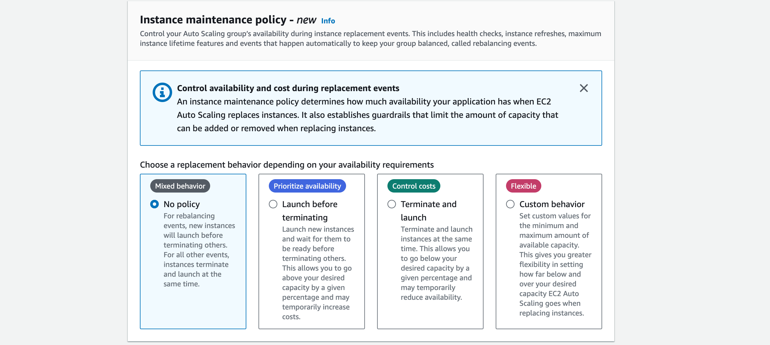
For maintenance policy, click no policy. Then click Next.
In this section, we will statically assign our auto scaling configuration. Note: You can configure dynamic scaling (add/delete an EC2 instance based off performance metrics or specific events, for example), but this is outside the scope of this workshop.
Set the following Group sizes (the ASG should always have 2 EC2 instances):
1. Desired Capacity: 2
2. Minimum Capacity: 2
3. Maximum Capacity: 2
Do not set a scaling policy (there will always be 2 EC2 instances unless the user changes the capacity manually. No dynamic scaling will be used).
Scaling Policy: None
Leave Enable instance scale-in protection unchecked.
Click Next.
Click Next without setting up notifications.
Add tags:
Click Next.
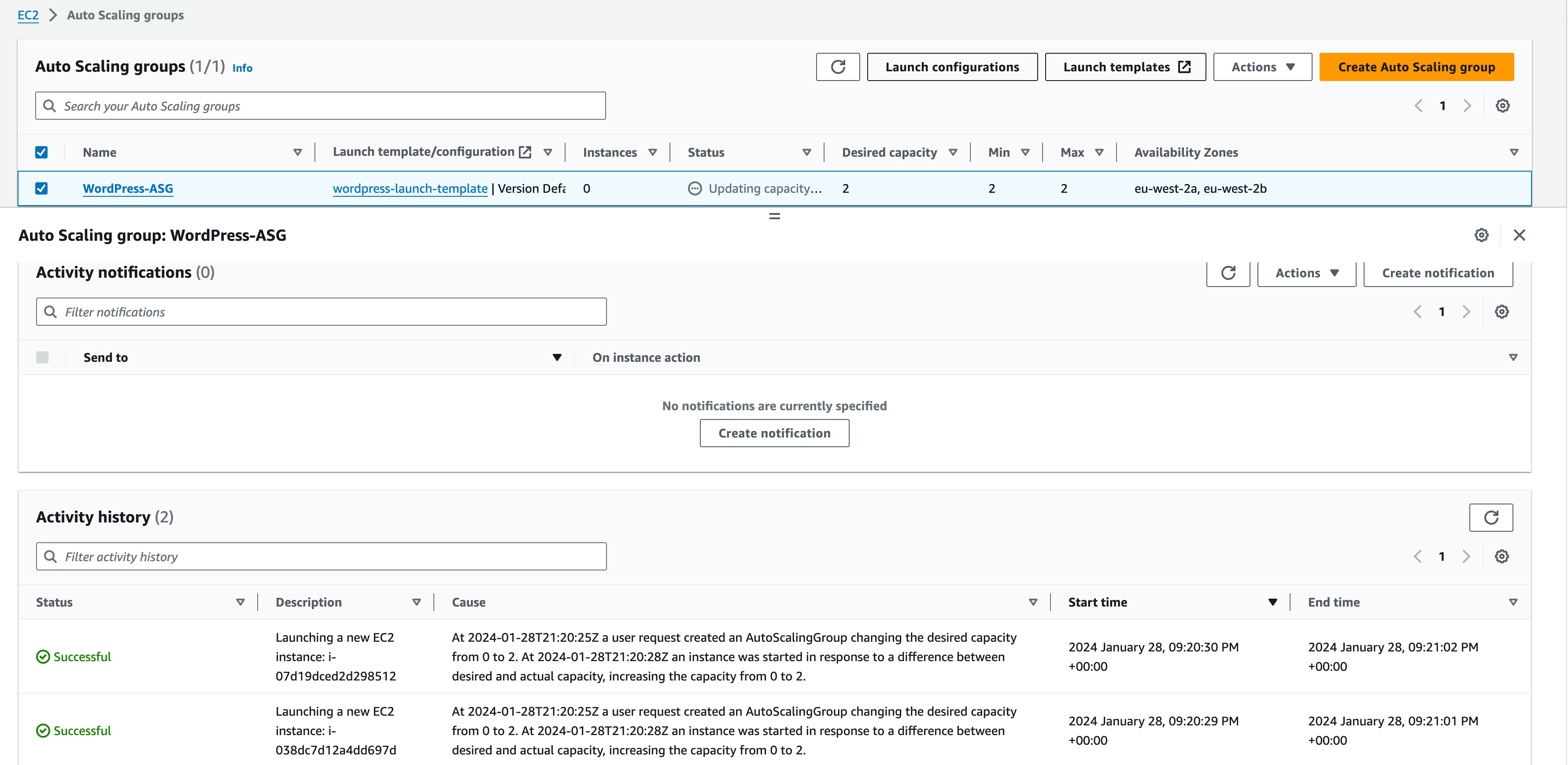
Double-check the details within the review section. Select Create Auto Scaling Group. The ASG will be created, and the Status will display “Updating capacity”. The EC2 instances are being provisioned.
Select the ASG.
Navigate to the Instance Management tab.
Note that 2 instances are being created as per our ASG capacity config.
Navigate to the Activity tab.
Under Activity History, we can see the events that triggered the scale. When an activity has been completed, the ‘Status’ will change to ‘Successful’. Click the ‘refresh’ arrow in the ‘Activity history’ section to make sure you are viewing the updated status, until both instances have launched successfully.
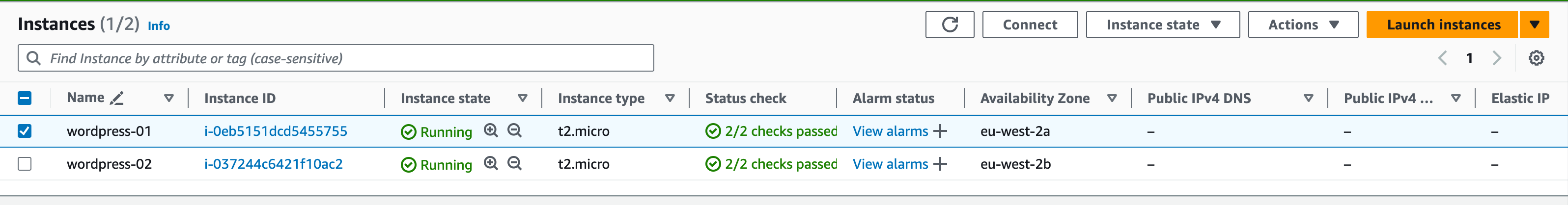
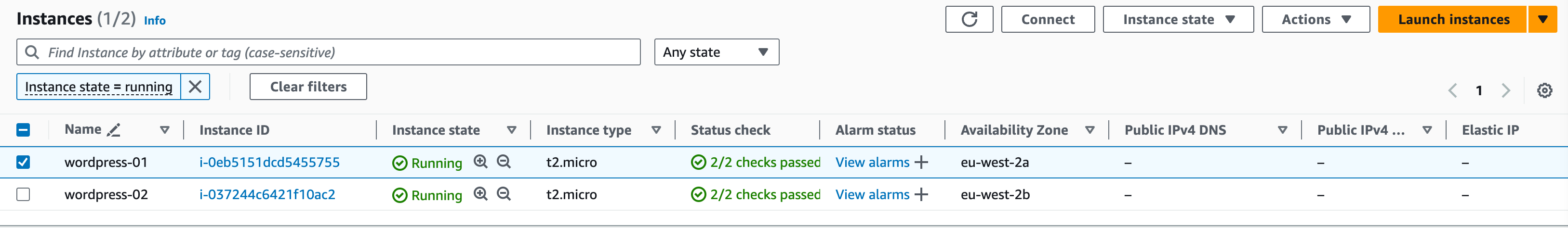
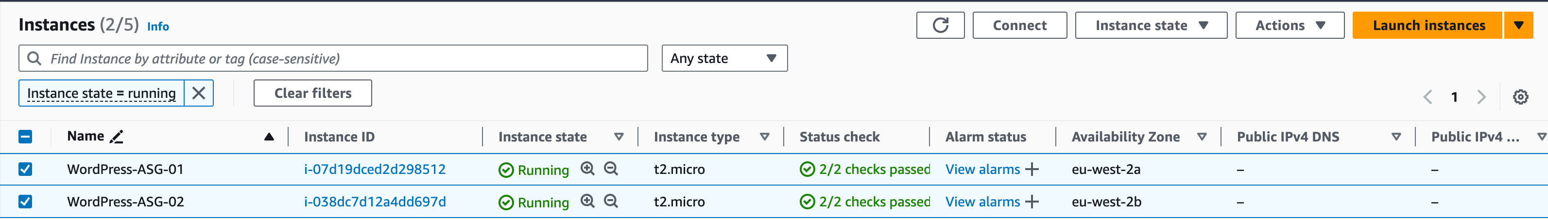
In the EC2 console, navigate to Instances. The ASG has created the EC2 instances, and they are available. You can name them to make them easier to identify, e.g. ‘WordPress-ASG-01’ and ‘WordPress-ASG-02′ (see screenshot below)
Application Load Balancer Using Auto Scaling Group
Once you have created the Auto Scaling Group and attached it to the Application Load Balancer, the Load Balancer will automatically register new instances created by the Auto Scaling Group.
1. In the EC2 console, navigate to Load Balancing –> Load Balancers.
2. Select the Listeners tab
Here we can view what port the ALB is listening on and what Target Group it’s forwarding its requests to.
Click on the name of the Target Group under the Rules heading (WordPress-Target-Group).
This will take us to the Target Group itself. Select the Target Group to obtain more information.
Select the Targets tab.
Here we can view the registered EC2 instances associated to it. Notice that we have our manually created EC2 instances (which we took an AMI copy of) along with the 2 nodes created by the Auto Scaling Group. (You may need to hit refresh to view the updated target group).
Ensure that the WordPress URL is accessible:
www.<inits>.url.com
The ALB forwards each request to a single EC2 instance in its backend. At this point in time, we have several instances that can accept the forwarded traffic and respond to the client. However, we have tested our AMI in a previous step we can safely remove any manually created EC2 instances from the Target Group.
Tick the box next to the manually created EC2 instances and click Deregister.
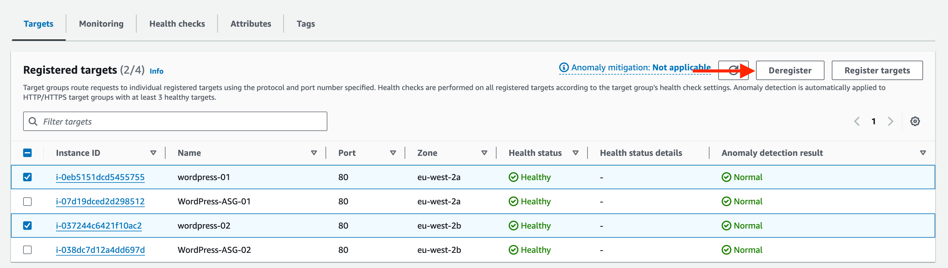
ii. This will drain the instance from the ALB Target Group (safely removes the instance without affecting traffic to WordPress – the ALB will route all traffic to the remaining 2 EC2 instances).
Check the WordPress URL again to see that the web page is still accessible during the drain process.
Once the draining has completed, 2 EC2 instances should be remaining, and these are now maintained by the Auto Scaling Group.
The drain only removes the WordPress EC2 instances from the Target Group, it does not delete it. The instance is still available in the Instances dashboard. You can now terminate the manually created instances by following these steps:
In the EC2 console, tick the names of your manually created instances (leave the instances created by the Autoscaling group). Click Instance state, then Terminate instance. You will see the instance state change.
Testing WordPress HA
In this section, we will test WordPress HA by stopping the httpd service on one of the instances. This will simulate a typical failure on the instance itself.
The Application Load Balancer performs health checks against each backend to determine which instances are available to receive forwarded traffic. This health check will also be used by the Auto Scaling Group to detect a failure within its group. If a failure is detected, the Auto Scaling Group will delete the failed instance and replace it by utilising the Launch Configuration, in line with its auto scaling configuration.
1. Log onto one of the WordPress instances
a. Connect to your WordPress Instance via SSM
b. Verify that the httpd service is available and running:
sudo service httpd status
Check the Target Group registered targets in the AWS console – the health status for both EC2s should be ‘healthy’.
3. On the WordPress terminal, stop and disable the httpd service.
- sudo systemctl disable httpd
- sudo service httpd stop
- sudo service httpd status
Check the Target Group registered targets again – refresh periodically if required until a health failure has been detected on the instance you modified.
5. Navigate to the WordPress URL to verify that the web page is still available.
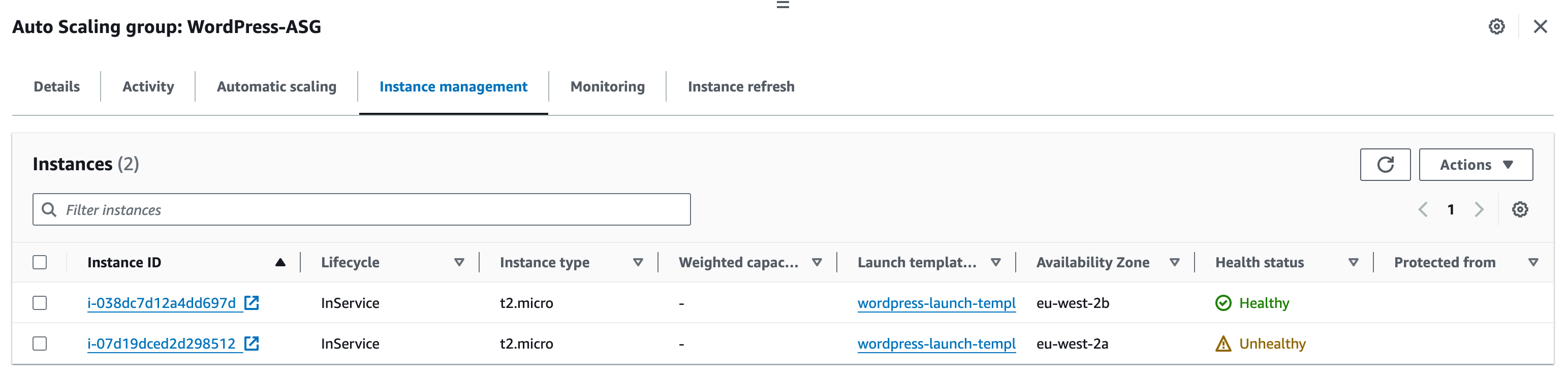
6. Navigate to the Auto Scaling Group. Select the Instance management tab.
a. Here you can see the instances managed by the ASG. Notice that one of the instances is marked as unhealthy.
7. Navigate to the Activity tab.
a. Refresh until we see a new activity
8. After some time, a new EC2 instance will be created and in a Healthy status. The failed EC2 instance will be terminated automatically.
9. On the EC2 Dashboard, navigate to Load Balancing –> Target Groups. Select the WordPress Target Group.
10. Under the Targets tab, refresh – notice that there are now 2 healthy instances. The Application Load Balancer can now forward WordPress traffic to both instances.
This has demonstrated how you can leverage AWS Cloud Services to facilitate High Availability for your EC2 instances.
The following workshop tasks will illustrate HA can be configured on other services, such as RDS and ElastiCache, which are both used as part of the overall WordPress solution. Proceed to the next section.
Configure HA for ElastiCache for Memcached
There are two types of failures to consider when planning your Memcached solution:
Node failure:
Spreading your cached data over multiple nodes ensures that the data is distributed evenly.
Replication is not supported, so if a node fails you lose that portion of cached data. Therefore, partitioning your data across a greater number of nodes means you lose less data when a single node fails.
Availability Zone failure:
Spreading your nodes across different Availability Zones ensures that not all nodes are lost if an AZ fails.
In the unlikely event of an AZ failure, you will lose the data cached on all nodes within that AZ, whilst the cached data in other AZs will remain unaffected.
In this workshop, we will configure our ElastiCache Memcached solution to consist of 2 nodes, both located in separate Availability Zones for High Availability.
Enabling HA for existing ElastiCache Memcached Cluster
- Modify the existing cluster:
- In the ElastiCache dashboard, select Memcached clusters.
3. Select the existing Memcached cluster click Actions and Modify.
4. Scroll down to Subnet group settings and click ‘Modify’.
5. Click ‘manage’.
6. Tick the box next to ‘eu-west-2b’. Save changes.
7. Click the three horizontal lines to expand the left pane.
8. Click ‘memcached clusters’ then the name of your cluster (memcached-cluster)
9. Scroll down to click the orange ‘Add nodes’ button
10. In ‘Number of nodes’, enter ‘1’ to add one node. Under Availability Zone placement, select Specify Availability Zones from the dropdown menu.
11. In the ‘Zone’ dropdown menu, select the zone that is currently not in use (e.g. eu-west-2b).
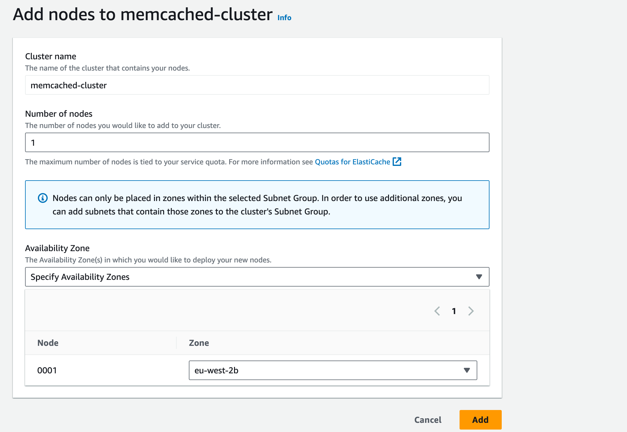
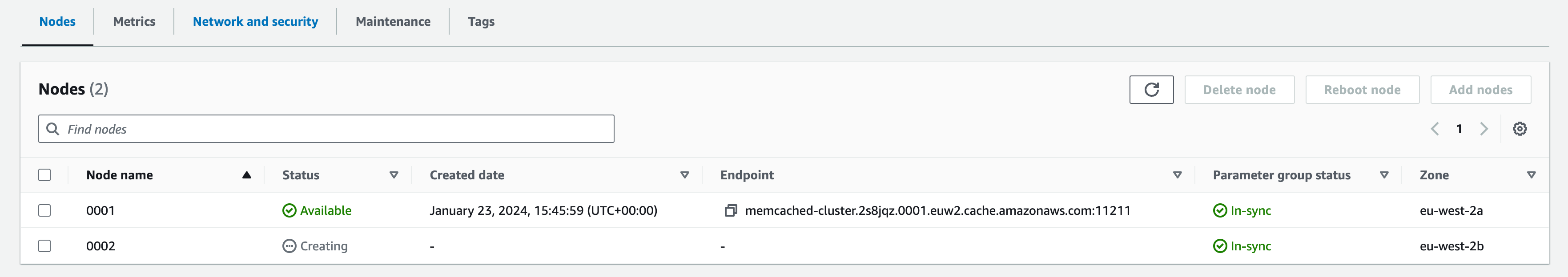
12. Click ‘Add’, a new node will be created in a separate Availability Zone.
13. The cache data will be partitioned between both nodes.
14. You have completed the HA configuration. The Memcached solution now tolerates a single node failure and a single AZ failure.
Setup SNS topic with an email address as an endpoint
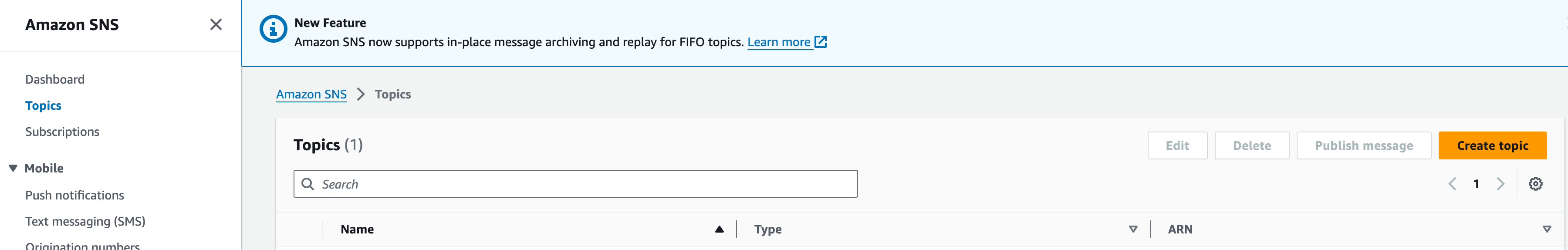
- Search for SNS in the console search bar
- Click on Topics in the left pane and then the Create Topic button on the right side of the screen
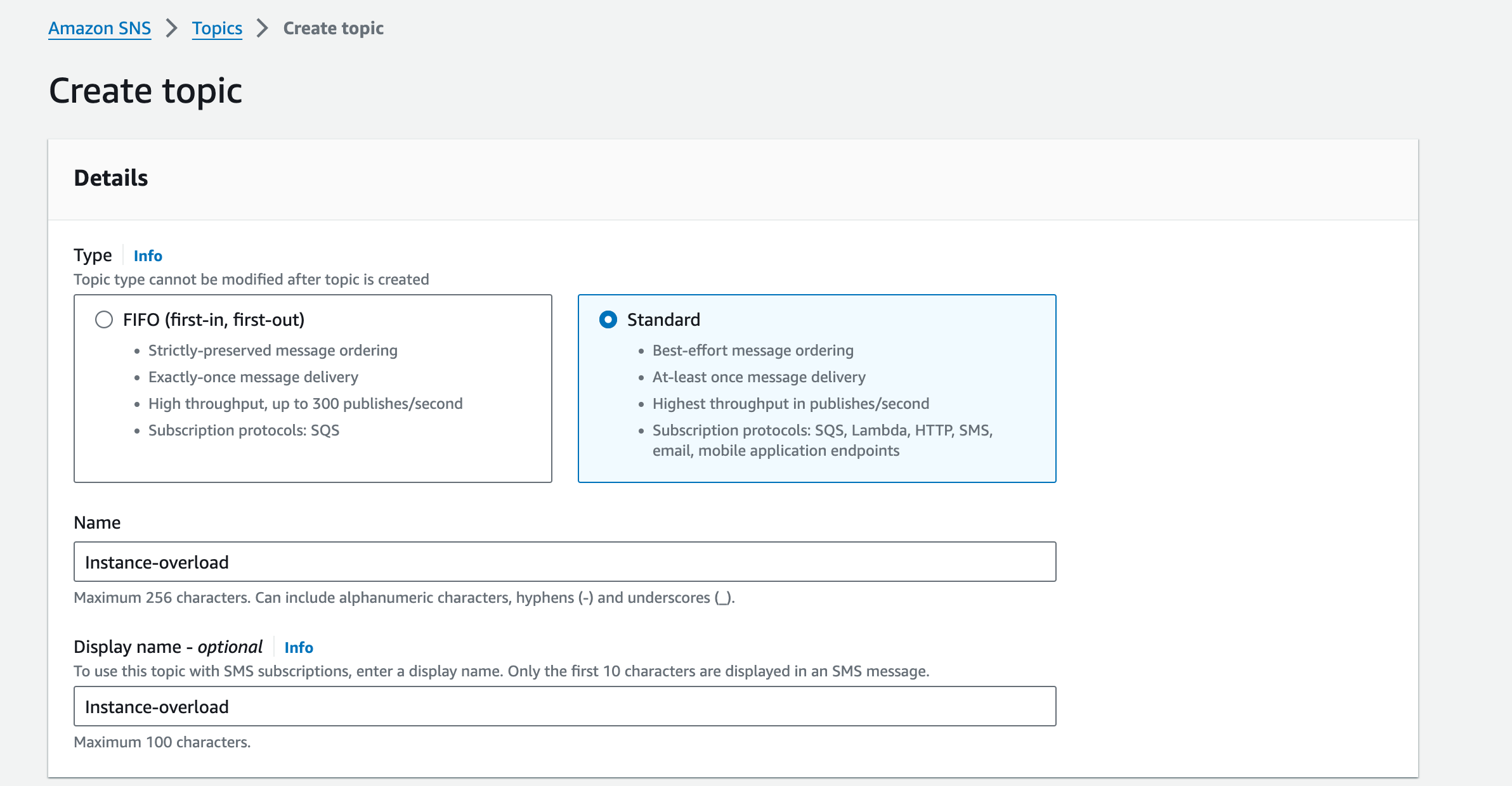
- Set the type to standard
- Give the topic a name (e.g., “Instance-overload”) and optionally a description
5. Leave the remaining sections and click on Create topic
6. In the left pane of the SNS console click on Subscriptions, then click Create subscription in the top right corner
7. Click on Topic ARN and select the SNS topic created in the previous steps
8. Under Protocol select ‘Email’, then enter your email address in the Endpoint field
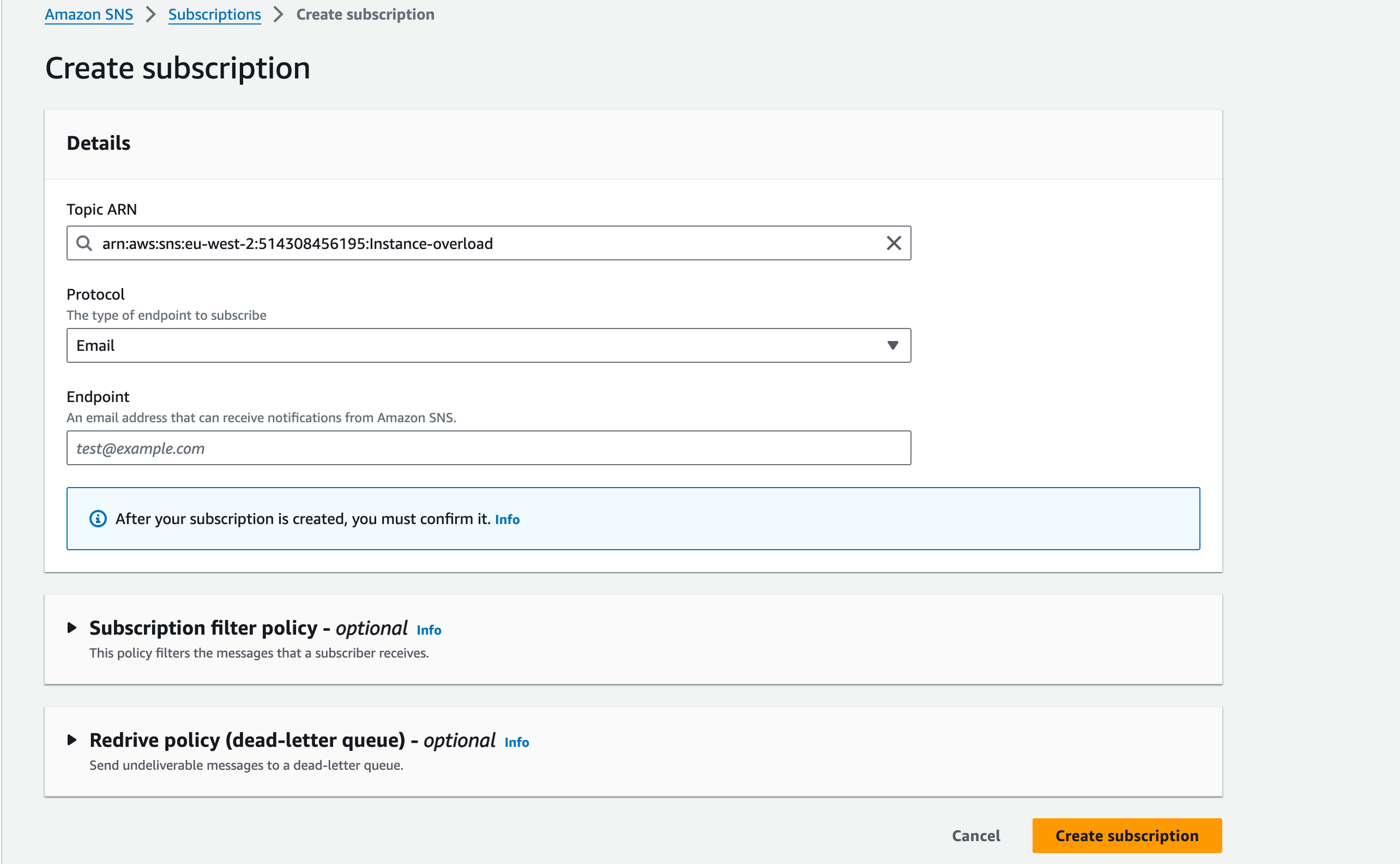
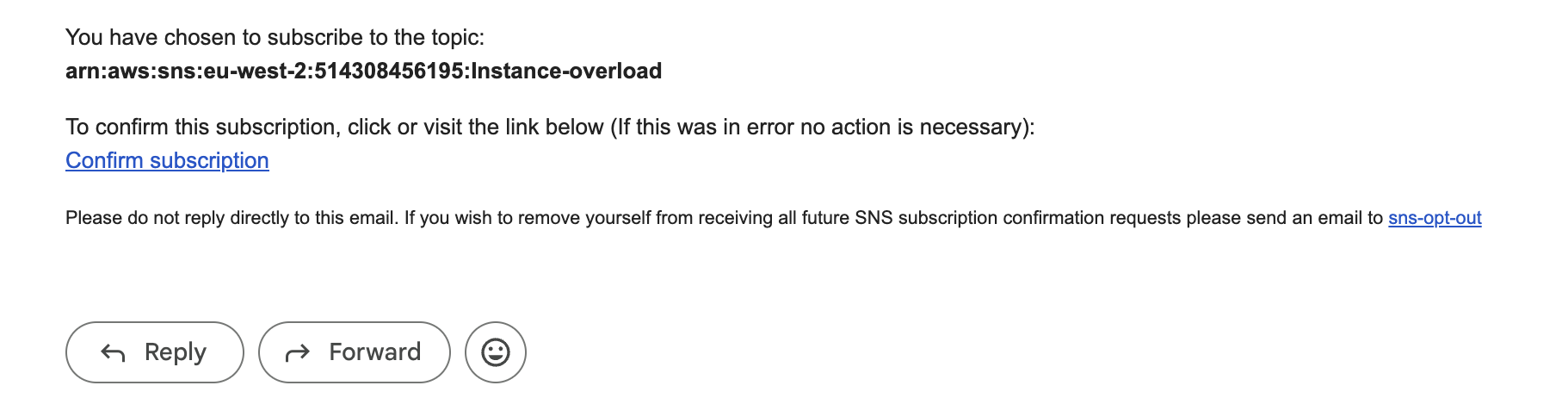
9. Click Create subscription. Note that you will receive an email with a confirmation link, you will need to open this before the endpoint can start receiving alarm notifications
Add IAM permissions to your instances to access CloudWatch
- The first thing that’s needed for the instance is an IAM role that allows communication with CloudWatch, the required policy is CloudWatchAgentServerPolicy
- To add this to your instance, go to the IAM console and click on Roles in the left blade
- Search for the instance profile created in workshop 2 (instance-iam-profile)
- Click on the name of the profile, the click on the ‘add permissions’ dropdown and select ‘Attach policies’
- Search for the CloudWatchAgentServerPolicy policy, tick the box next to it, then click ‘Attach policies’.
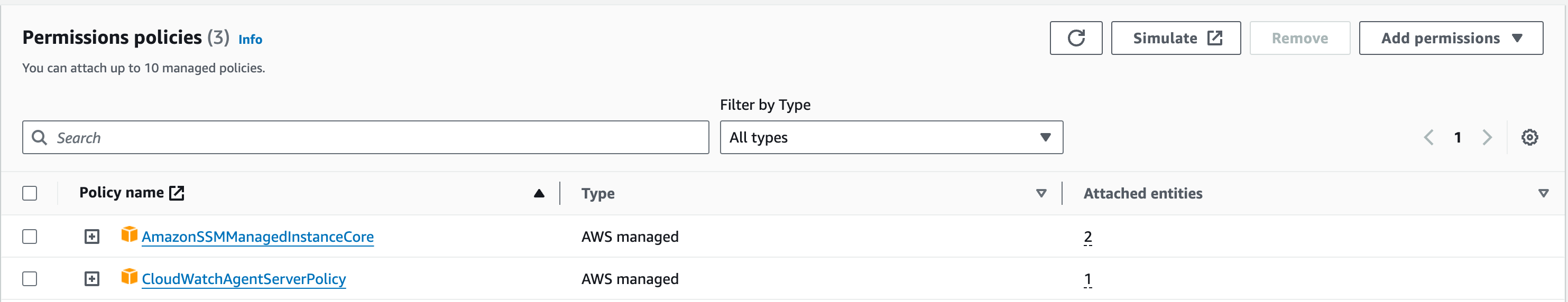
Install the CloudWatch Agent
- To install the CloudWatch agent, go to the SSM (Systems Manager) console. Make sure you are using the London Region (eu-west-2) then select Run Command from the left blade, then the Run a command button
- Search for AWS-ConfigureAWSPackage and select it from the list.
- In the Command parameters section, leave the Action as Install and enter AmazonCloudWatchAgent in the Name field
- In the Targets section select Choose instances manually, then select your instances from the list below. If the instances are not shown, use the search bar to search by ‘Node ID’, copy and paste each WordPress Squid-proxy Instance ID from the EC2 console into the search bar, then select the instance.
- Untick Enable an S3 bucket from the Output options and click Run
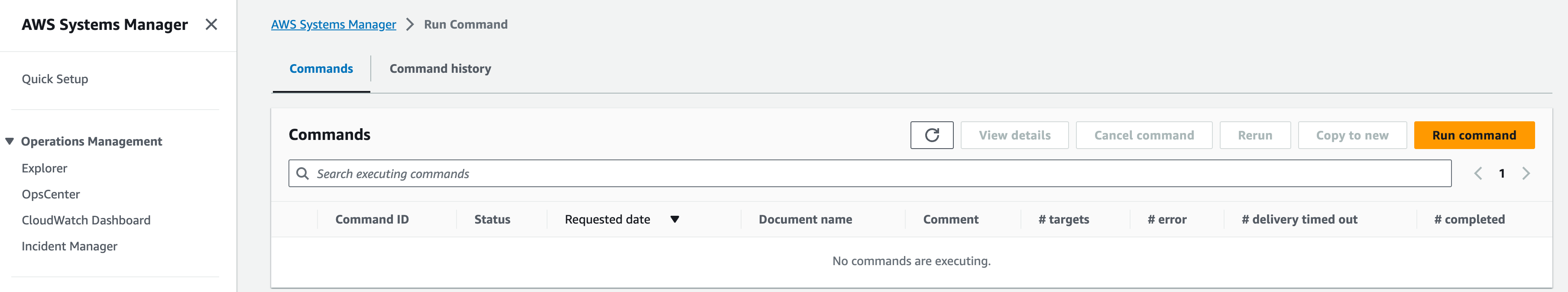
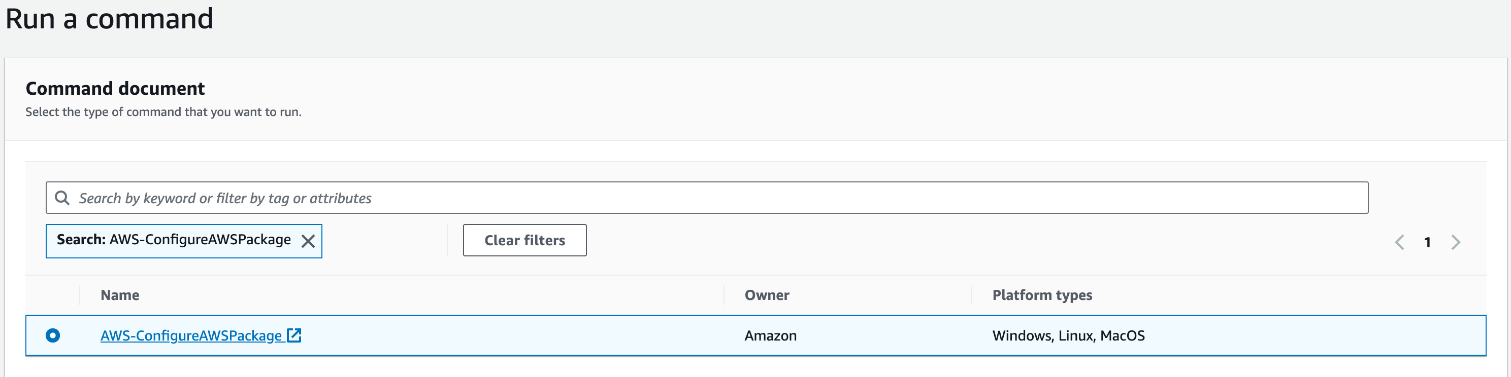
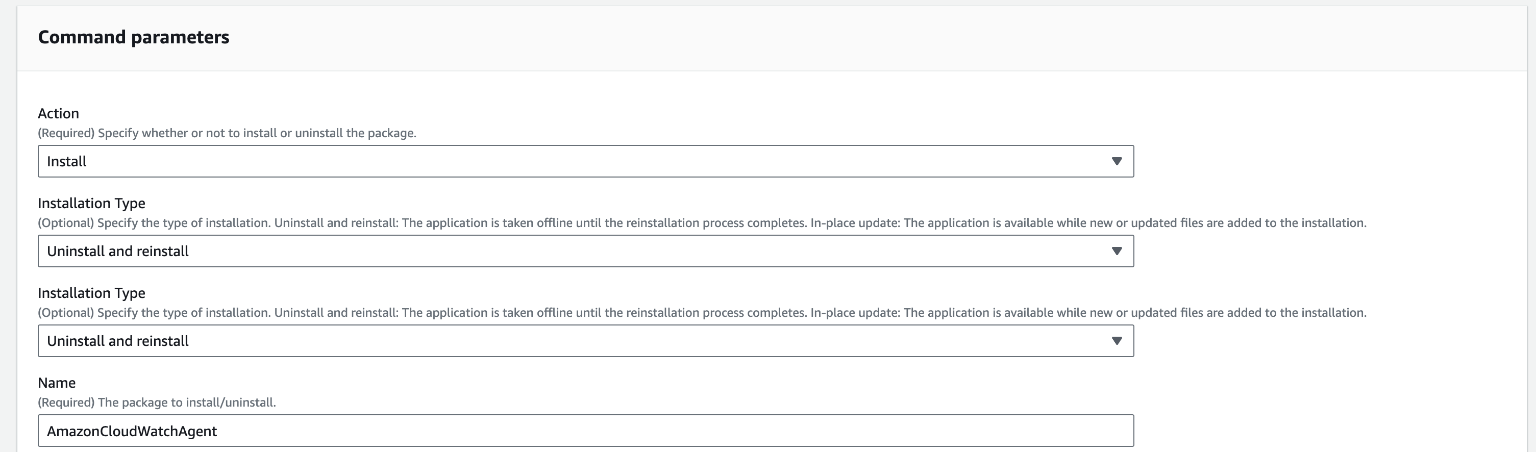
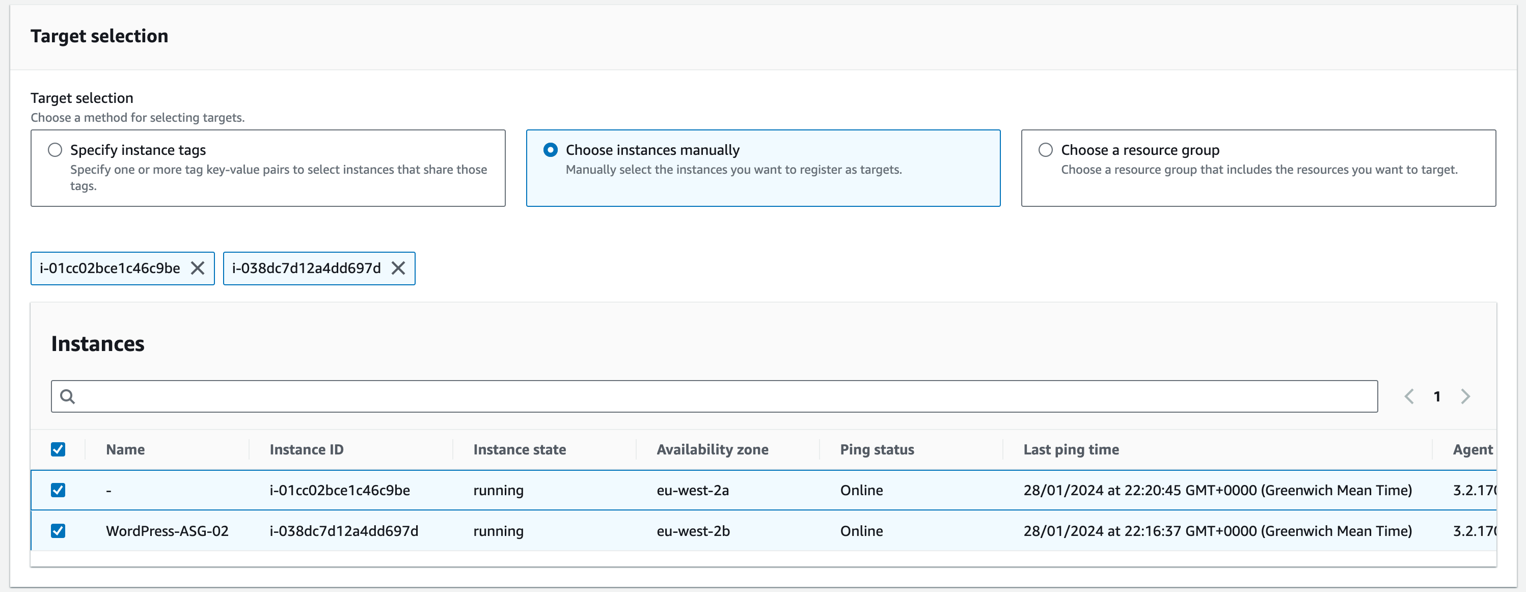
Configure the CloudWatch Agent
- Connect to your WordPress-01 EC2 instance via SSM and run the following command to launch the agent configuration wizard:
sudo /opt/aws/amazon-cloudwatch-agent/bin/amazon-cloudwatch-agent-config-wizard
2. Once the wizard starts, select the following options to create the config file and collect host metrics: (type in the number and hit ‘enter’ to input your selection – see screenshot)
Install on Linux – 1
Collect information from EC2 metadata – 1
Run as root – 1
Turn on StatsD daemon – 1
Use default port – 8125 (just hit ‘enter’to choose this port as it is already selected as the default choice)
Collect at 10 second intervals – 1
Aggregation interval 60 seconds – 4
Do not monitor metrics from CollectD – 2
Monitor Host metrics – 1
Do not monitor CPU metrics per core – 2
Add EC2 dimensions – 1
Aggregate EC2 dimensions – 1
Collect metrics at 60 second resolution – 4
Choose basic metrics – 1
This will preview the config file in JSON format (see screenshot below), if all looks correct then select yes – 1
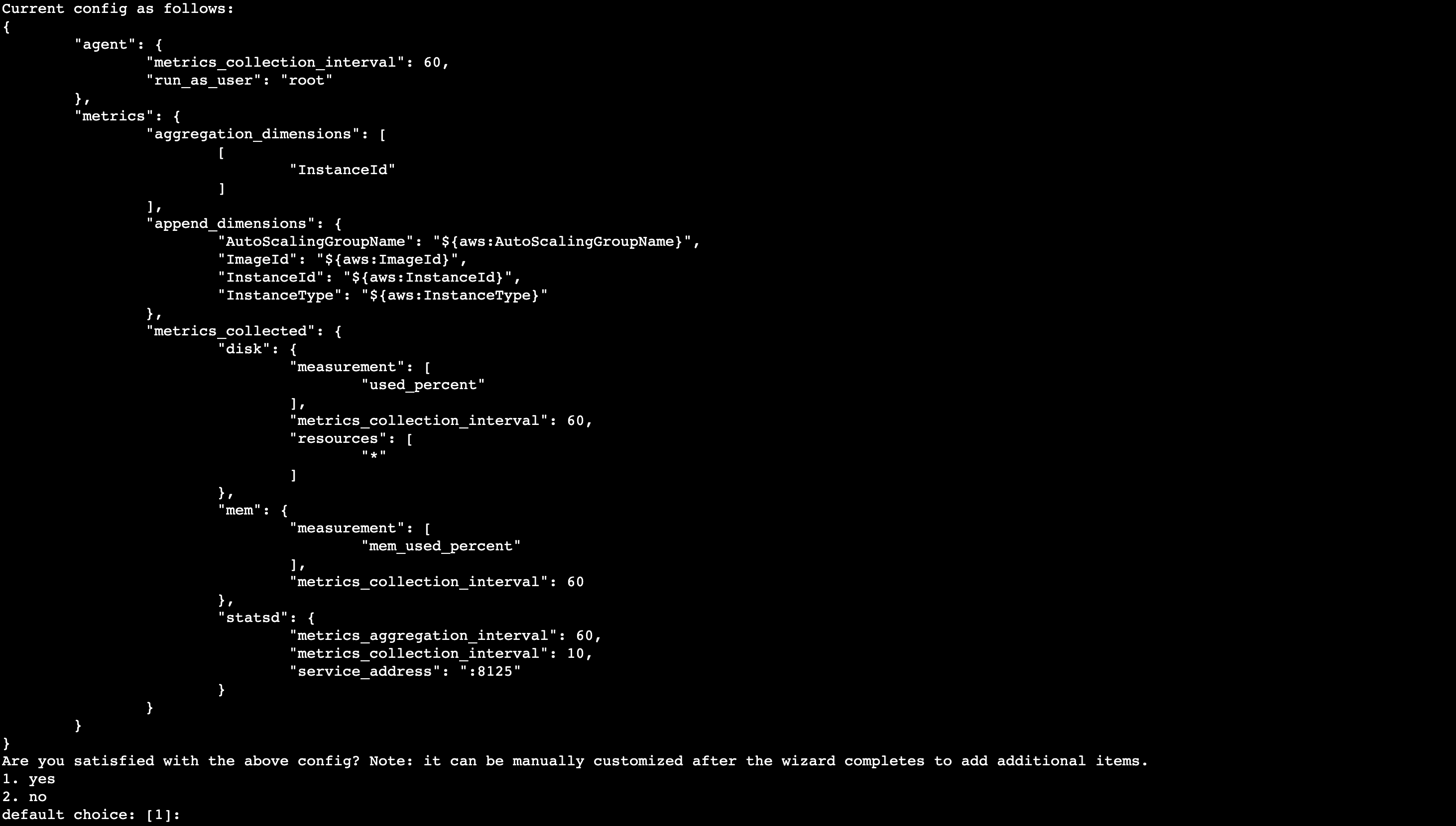
Select no for existing config file to import – 2
Do not monitor any log files – 2
Do not store the config in the SSM parameter store – 2
3. Start CloudWatch agent by running the following command
sudo /opt/aws/amazon-cloudwatch-agent/bin/amazon-cloudwatch-agent-ctl -a fetch-config -m ec2 -s -c file:/opt/aws/amazon-cloudwatch-agent/bin/config.json
4. You can confirm the agent service is running by running the following command
sudo systemctl status amazon-cloudwatch-agent
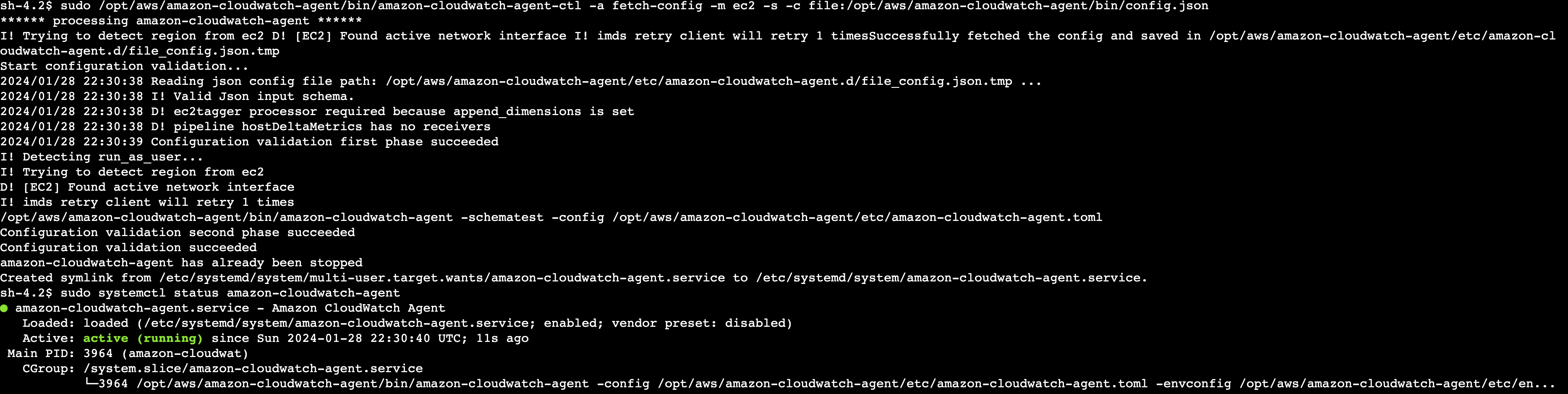
Repeat the steps above for WordPress-02 to configure the Cloudwatch Agent.
Create CloudWatch alarms and send alert to SNS topic
- Search for Cloudwatch in the Console search bar
- Once the service is selected, click Alarms, then click All alarms in the left pane, then Create alarm in the top right
- Click Select metric then scroll down to the Metrics section. In the AWS namespaces section select EC2
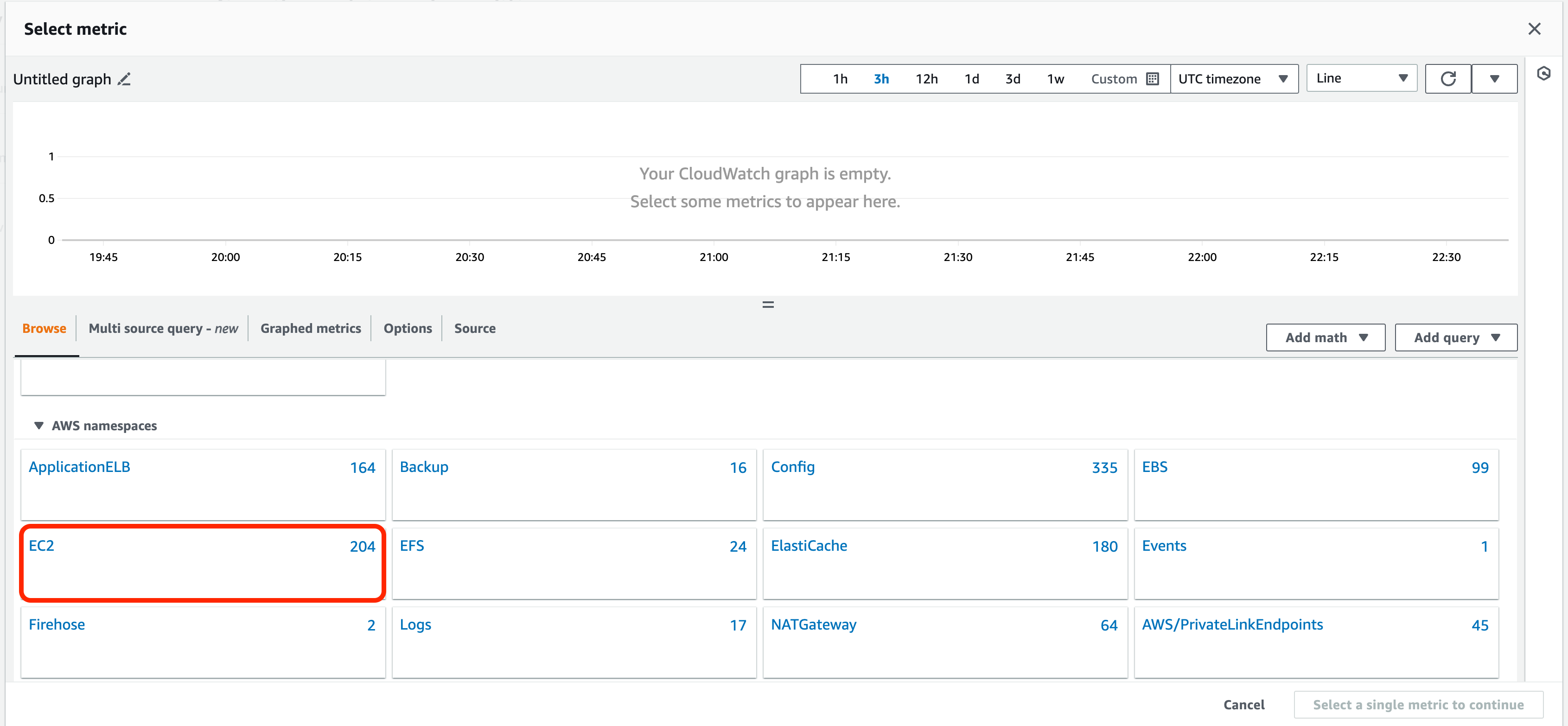
4. Click Per-Instance Metrics and then search for your instance ID in the search bar or scroll down until you find the Squid-proxy-01 instance. You will see that several Metric names are listed.
5. Select the Metric you want to create an alarm for, in this case it will be CPUUtilization, then click Select metric
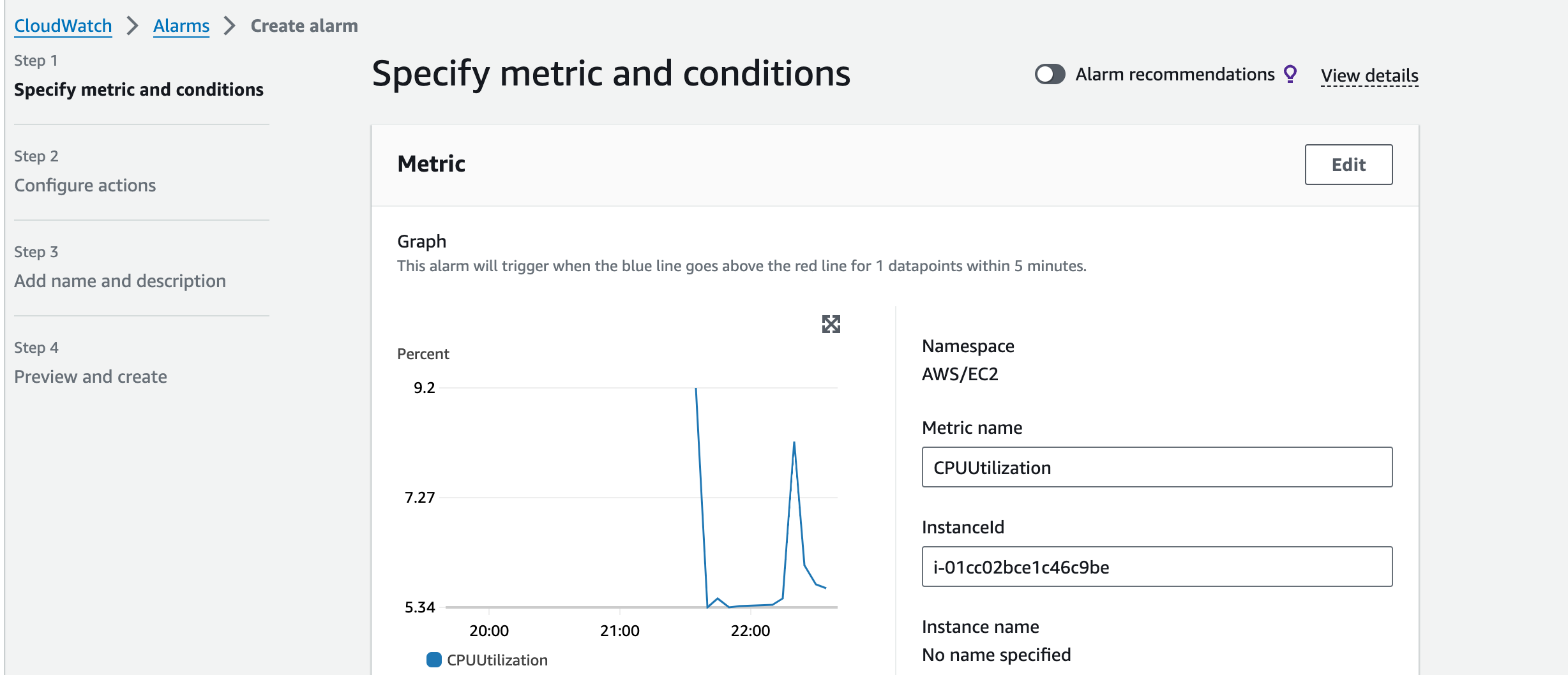
6. On the metrics and conditions page, change the period to 1 minute
7. Leave the conditions section as default except for the threshold value, set this to 80, then click Next
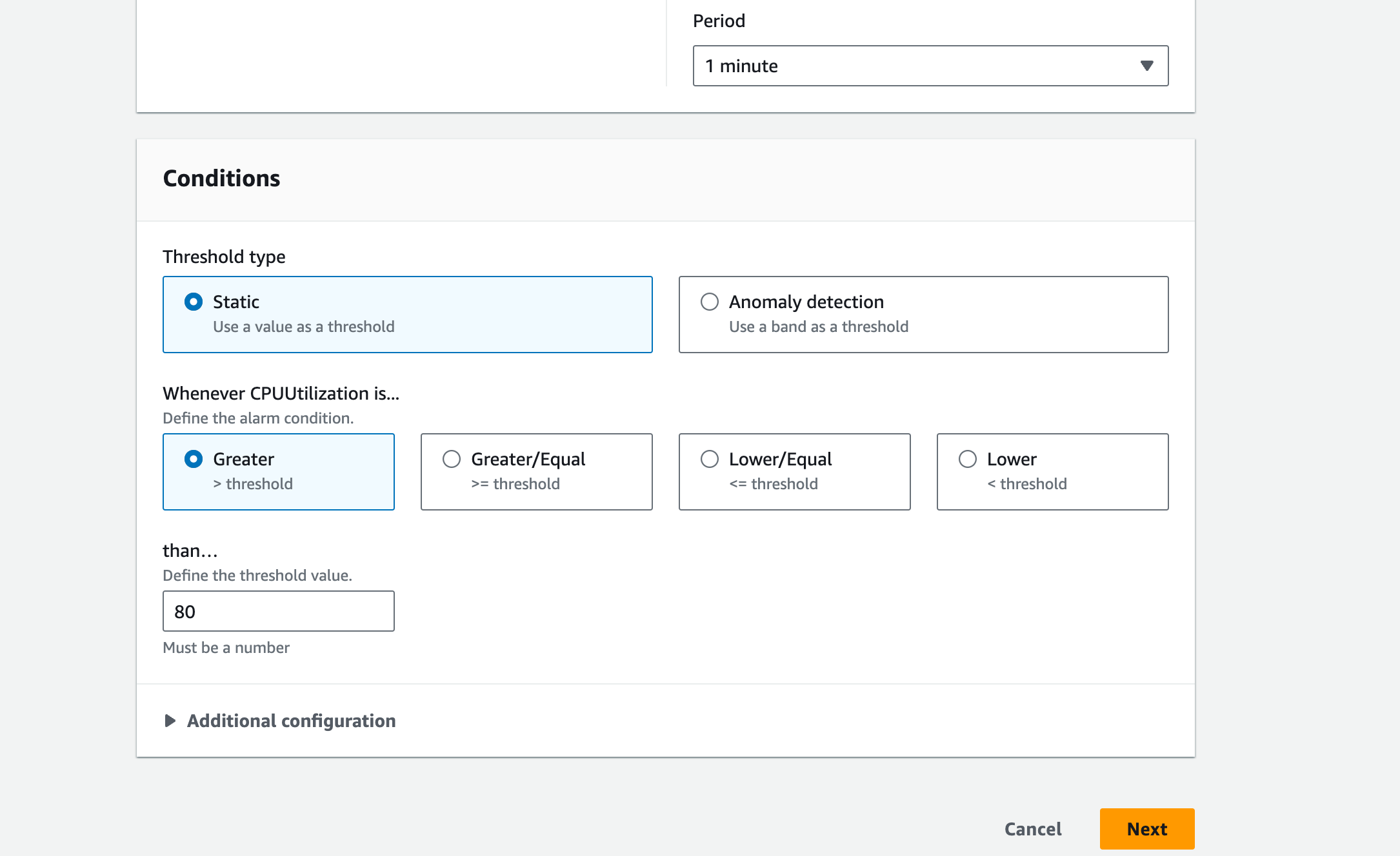
8. In the Configure actions section, leave the settings as default except for the “Send a notification to…” field, click on this and select the SNS topic (instance-overload) created in the previous section. You will need to select ‘instance overload,’ click it again so that it displays the arn (see screenshots below).Scroll down and hit next.
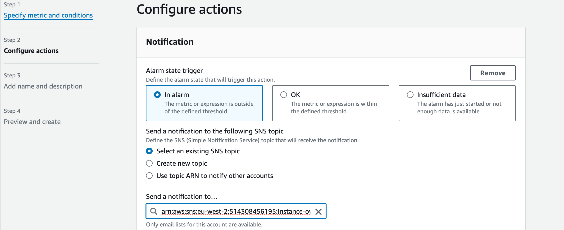
9. Give the alarm a name and optionally a description
Name: Instance-WP-01-CPU-High
Description: Alarm for when an instance reaches more than 80% CPU utilisation
Click ‘next’
10. Review the settings and click Create alarm
11. To create Alarms for the CloudWatch agent metrics go back to All Alarms, then click Create alarm
12. Click ‘Select Metric’ then select CWAgent from the Custom namespaces section
13. Under Metrics, click on CWAgent > InstanceId (there should be 2 metrics for each WordPress EC2 instance: mem_used_percent and disk_used_percent)
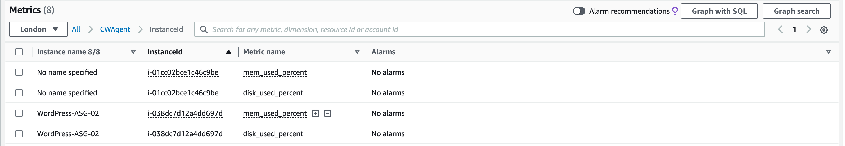
14. Select the memory metric (mem_used_percent) for the WordPress-01 EC2 instance and then click Select Metric
15. Set the period to 1 minute
16. Leave the Conditions section as default except for the threshold value, set this to 80
17. Click Next to go to the Notifications section
18. Select the SNS topic previously created as the notification endpoint (again, make sure the ARN is listed)
19. Click Next and give the alarm a name and optionally a description (e.g. name: instance-sp01-mem-high, description:alarm for when an instance reaches more than 80% memory usage)
20. Review the settings and click Create alarm
21. Repeat steps 10 to 18 for the disk_used_percent metric for WordPress-01.
22. Repeat all steps in this section to configure all alarms for WordPress-02.
See screenshot with all alarms: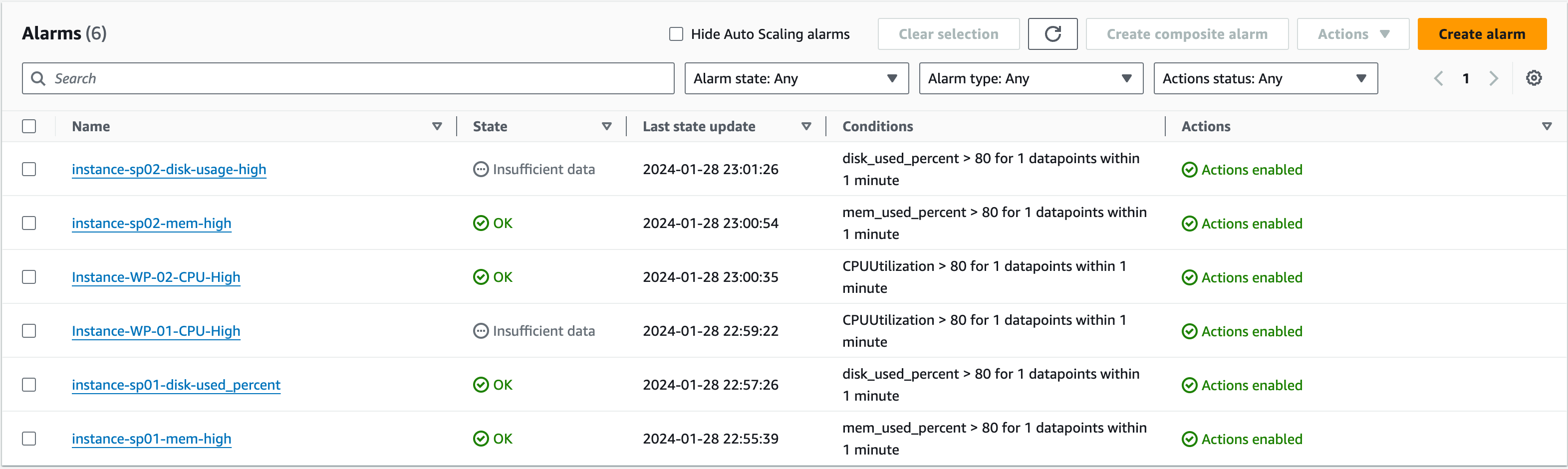
Trigger an alarm by overloading an instance
In this section we will trigger one of the alarms by forcing an instance to breach the alarm threshold.
- Open a SSM session to the WordPress-01 EC2 instance
- Install the Stress tool using the following commands
sudo amazon-linux-extras install epel -y
sudo yum install stress -y
3. Once the installation is completed, run the following command to overload the CPU
sudo stress --cpu 8 --timeout 10m
4. If you click on the Monitoring tab of the EC2 instance and enlarge the CPU chart, you should be able to see the load spiking.
5. You can also view the alarm in the CloudWatch console to see how close it is to the threshold.
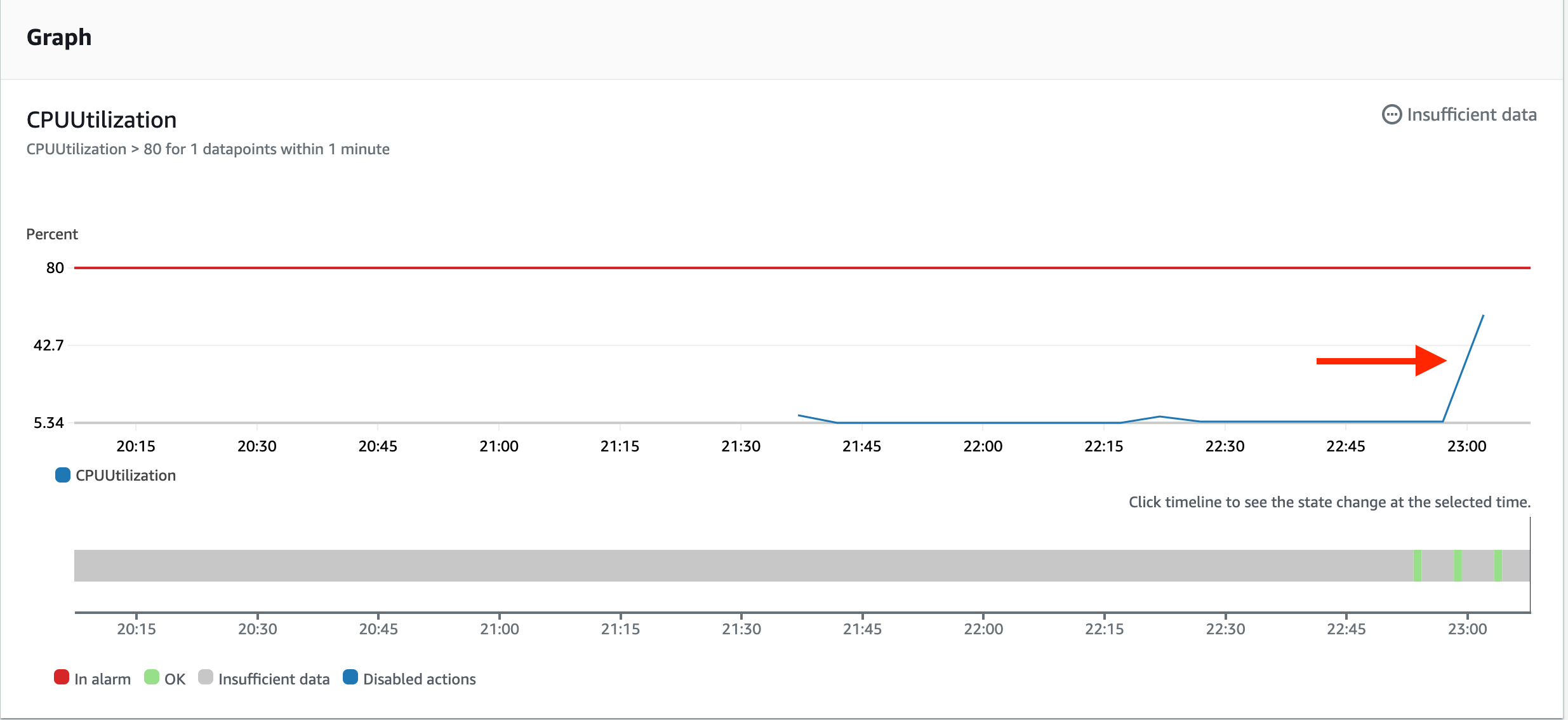
6. Once the threshold is reached, you should receive an email to your topic endpoint from AWS Notifications, alerting you that the alarm has been triggered.
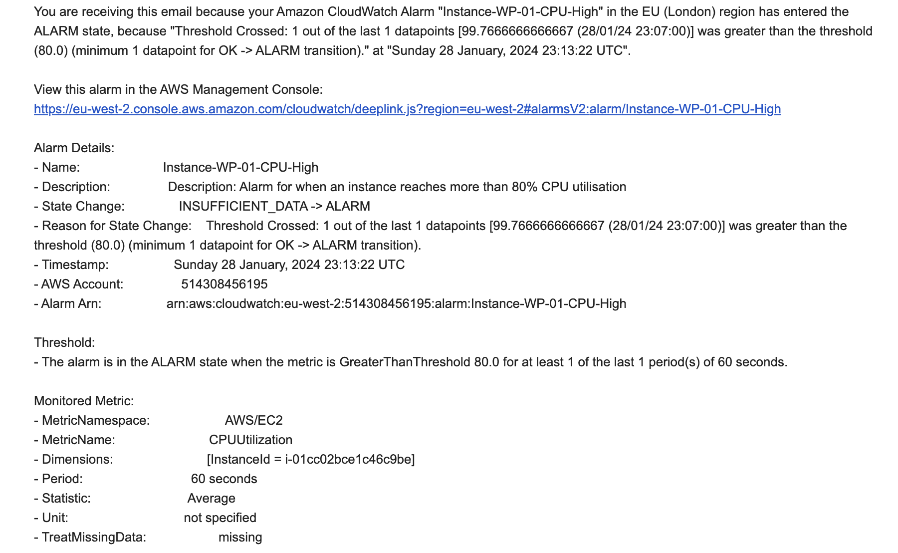
Creating VPC endpoint for private instances
Our instances can connect to the internet via the routing from Private Subnets to Public Subnets and the NAT Gateways. However, we will learn another method for EC2 instances in private subnets to connect to SSM, for times when your architecture does not include NAT Gateways, by creating VPC endpoints for private instances. To allow session manager to connect to instances that do not have an internet connection, the use of VPC endpoints will be required. There are 3 in total, but they all follow the same steps to configure.
- First, a security group is required. Create a new security group by going to the EC2 console and selecting ‘Security Groups’ from the ‘Network & Security’ section of the left pane.
- Click ‘Create security group’:
- Security group name: ‘ssm-endpoint-sg’
- Description: ‘Allow communication to SSM endpoints on port 443’
- VPC: VPC-A
- In the ‘Inbound rules’ section, click ‘Add rule’
- Create an inbound rule that allows traffic on port 443 from the VPC CIDR (10.0.0.0/16) – type: HTTPS, port range: 443, Destination: custom, CIDR block ‘10.0.0.0/16’
- Leave the default outbound rule and click Create security group
- Navigate to the VPC console by using the search bar, select Endpoints from the left pane, then click the Create endpoint button in the top right
- Give the endpoint a name (e.g., “ssm-endpoint”)
- Leave AWS services selected and then select com.amazonaws.eu-west-2.ssm from the services list below. Click the dot next to the service name to select it.
- Select your VPC from the VPC list (VPC-A)
- In the Subnets section, select both availability zones you have deployed subnets into, then choose the Private-Subnet-(APP)-01 and ‘Private-Subnet-(APP)-02’ from the dropdown menu on the right.
- Choose the security group created on step 6, then click Create endpoint at the bottom of the screen.
- Repeat steps 10 to 15 for com.amazonaws.eu-west-2.ssmmessages and com.amazonaws.eu-west-2.ec2messages
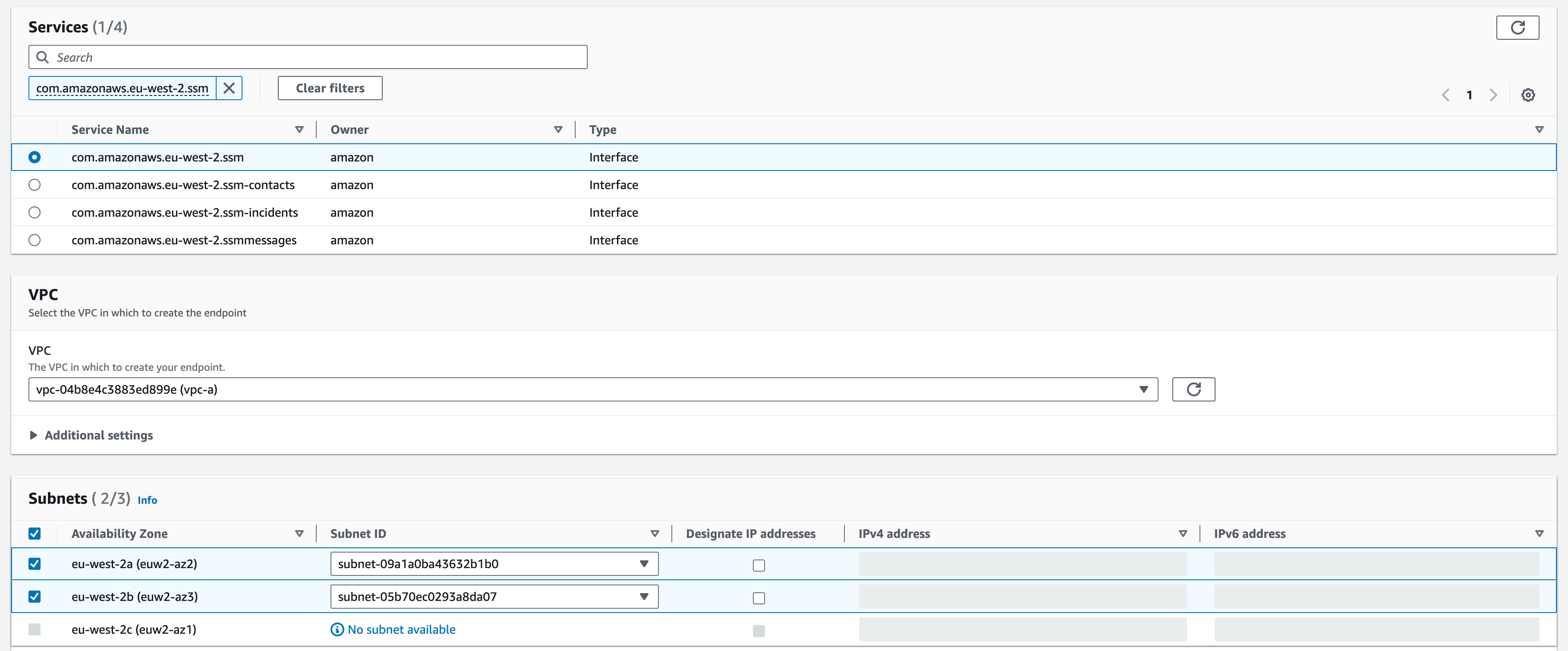
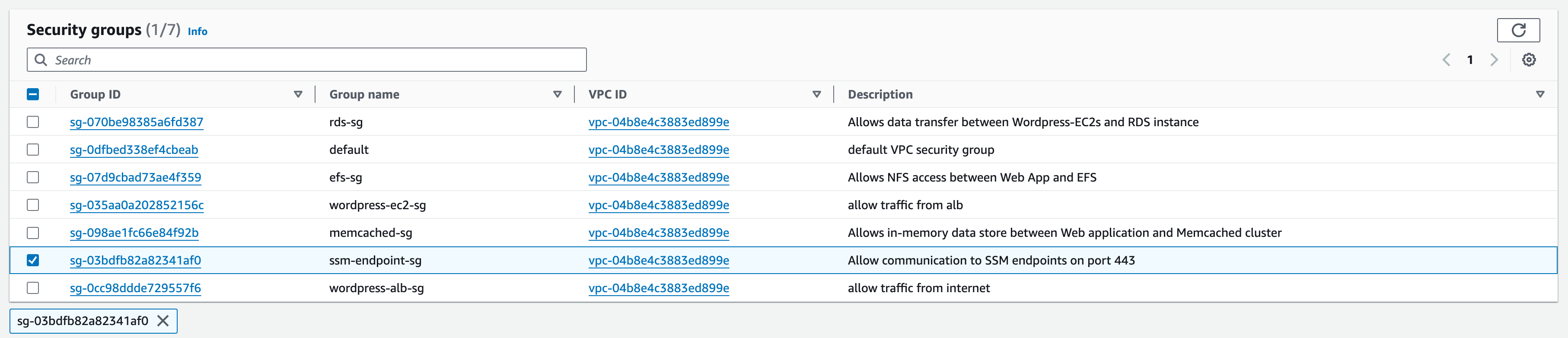
One approach could be to individually delete each EC2 instance hosting your WordPress site. However, this will not work because of the Auto Scaling Group (ASG) we have configured. If one instance is terminated, the ASG will automatically spin up a new instance to maintain the desired number (2 in this case).
Therefore we need to delete the Auto Scaling Group itself. Find the group and take the necessary steps to delete it.
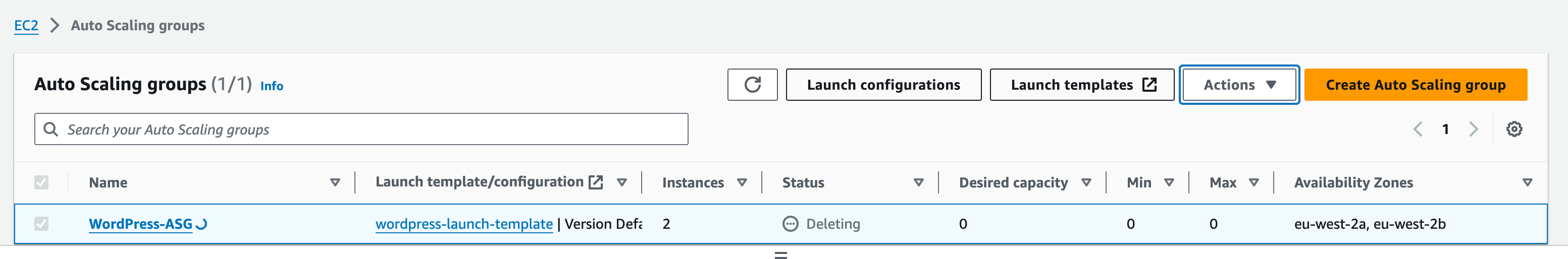
To delete your Amazon RDS instance, navigate to the RDS Databases page in the AWS console. Find your WordPress Amazon RDS instance and select it. Then, select Actions and Delete.
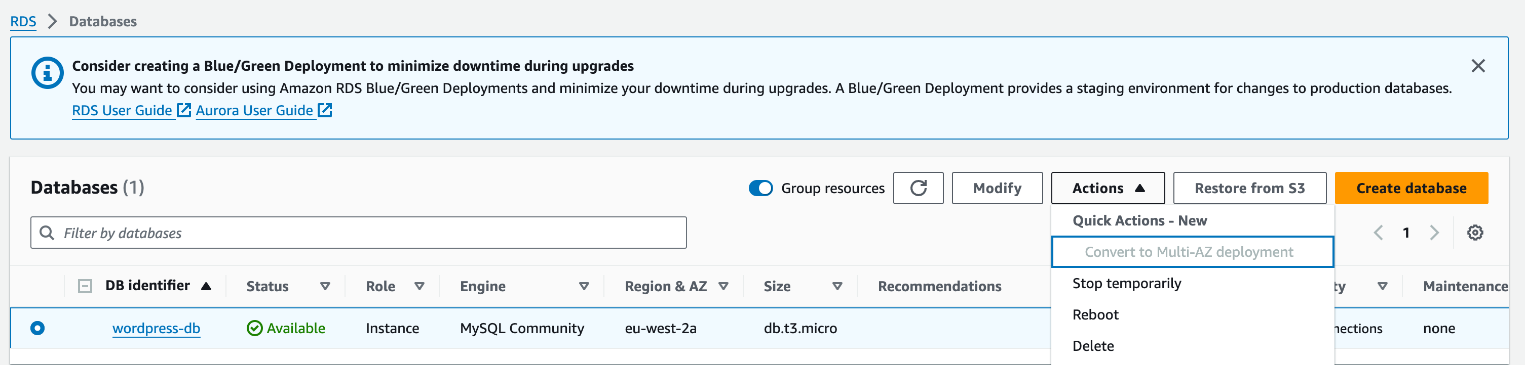
Enter delete me into the confirmation box and choose the Delete button to finalize the process.
Delete the Amazon CloudFront distribution.
Before you delete an Amazon CloudFront distribution, you must disable it. A disabled distribution is no longer functional and does not accrue charges. You can enable a disabled distribution at any time. After you delete a disabled distribution, it is no longer available.
To disable and delete a CloudFront distribution
- Open the CloudFront console at https://console.aws.amazon.com/cloudfront/v3/home.
- Select the distribution that you want to disable, and then choose Disable.
- When prompted for confirmation, choose Yes, Disable.
- Select the disabled distribution, and then choose Delete.
- When prompted for confirmation, choose Yes, Delete.
Delete the Route 53 hosted zone.
Before you delete the hosted zone, you must delete the record sets that you created. You don’t need to delete the NS and SOA records; these are automatically deleted when you delete the hosted zone.
To delete the record sets
6. Open the Route 53 console at https://console.aws.amazon.com/route53/.
7. In the list of domain names, select your domain name, and then choose Go to Record Sets.
8. In the list of record sets, select the A records that you created.
9. The type of each record set is listed in the Type column.
10. Choose Delete Record Set.
11. When prompted for confirmation, choose Confirm.
To delete a Route 53 hosted zone
12. Continuing from the previous procedure, choose Back to Hosted Zones.
13. Select your domain name, and then choose Delete Hosted Zone.
14. When prompted for confirmation, choose Confirm.
Disable logging and delete your S3 bucket
Before you delete your S3 bucket, make sure that logging is disabled for the bucket. Otherwise, AWS continues to write logs to your bucket as you delete it.
To disable logging for a bucket
15. Open the Amazon S3 console at https://console.aws.amazon.com/s3/.
16. Under Buckets, choose your bucket name, and then choose Properties.
17. From Properties, choose Logging.
18. Clear the Enabled check box.
19. Choose Save.
Now, you can delete your bucket. For more information, see Deleting a bucket.
(Source: https://docs.aws.amazon.com/AmazonS3/latest/userguide/getting-started-cleanup.html, accessed 27/1/23)
Here is the recommended order:
- CloudFront Distribution
- S3 Bucket
- Route 53 Records
- Auto Scaling Group
- Application Load Balancer
- EC2 Instances & AMIs
- ElastiCache Cluster
- RDS Database
- EFS File Systems
- Security Groups
- Subnets
- Route Tables
- Internet & NAT Gateways
- VPC